
Connection Area of the Battery Management System
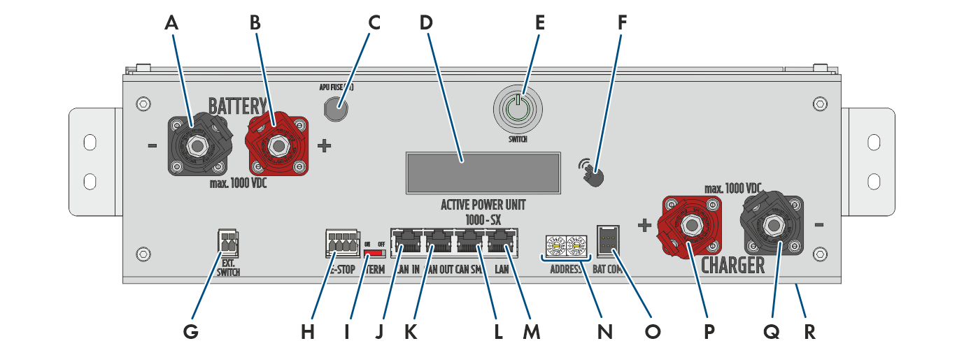
Connections on the battery management system
Position | Designation |
|---|---|
A | BATTERY -: DC connection on the battery for the negative pole (black) |
B | BATTERY +:DC connection on the battery for the positive pole (red) |
C | APU Fuse (F1): Fuse element for protecting the battery management system Operation is not possible if the fuse is defective. |
D | DISPLAY: Display for information, warnings, and errors |
E | SWITCH: On/off locking button on the battery management system |
F | MARKIERUNG: Marking for activating the display and switching the display by tapping (e.g., for retrieving the IP address of the battery management system). |
G | EXT SWITCH: Connection of the external switch to the control cabinet door of the battery cabinet |
H | E-STOP: 4-pole connector for the optional connection of an OFF switch for fast shutdown (already pre-mounted with bridge in default setting) |
I | TERM: Slider for setting the address on the battery management system (only for systems with more than one battery cabinet) |
J | CAN IN: Input for communication between primary and secondary battery cabinets (only for systems with more than one battery cabinet) |
K | CAN OUT: Input for communication between primary and secondary battery cabinets (only for systems with more than one battery cabinet) |
L | CAN SMA: Not used |
M | LAN: Modbus TCP/IP transfer for communication between battery and inverter |
N | ADDRESS: Two rotary switches for setting the address on the battery management system (only for systems with more than one battery cabinet) |
O | BAT COM: Communication connection to the first battery module, 6-pole |
P | CHARGER +: DC connection of the inverter or DC distributor for the positive pole (red) |
Q | CHARGER -: DC connection of the inverter or DC distributor for the negative pole (black) |
R | GROUND: Ground connection (stud bolt M6 on the back of the device) |