
Commissioning the Primary Battery Cabinet
 Qualified person

Performing system registration
To complete commissioning, a system registration must be performed
- Use the following link for the system registration: https://my.sma-service.com/.
Requirements:
The inverter has been correctly mounted and connected.
The inverter enclosure cover is securely closed.
The battery has been correctly mounted and connected.
All battery cabinets are securely closed.
The supplied energy meter has been correctly mounted and connected (see manual for the energy meter).
The DC distributor has been correctly mounted and connected (see manufacturer’s manual).
The secondary battery cabinets have been commissioned.
Procedure:
- If the battery is not commissioned within six months of manufacture or cyclization, request recyclization of the battery storage system. Contact the Service.
- If a SMA Data Manager M is available, activate the SMA Data Manager M (see manual for the SMA Data Manager M).
- Measure the room temperature in the battery room and the surface temperature of the battery module enclosures (e.g., with a laser thermometer).
- If the room temperature in the battery room and the surface temperature of the enclosures differ by more than 10°C, wait until the temperature difference falls below 10°C.
- On the primary battery cabinet, press the external switch on the outside of the cabinet door.
- On the battery management system of the primary battery cabinet, press the SWITCH control element.
- Activate the display on the battery management system. To do this, tap with the fingers on the highlighted area beside the display.
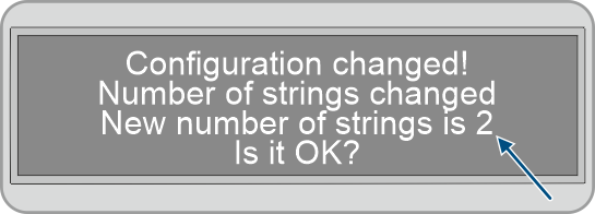
- The display on the primary battery cabinet shows the number of battery cabinets detected (Number of Strings). If, for example, a primary and a secondary battery cabinet were installed, the display would show Number of Strings = 2.
- If the number of battery cabinets detected does not match the number of battery cabinets installed, disconnect the battery from the voltage source Disconnecting from voltage sources and check all CAN communication connections.
- If the number of battery cabinets detected is still incorrect after eliminating any CAN communication faults, contact Service.
- If the number of battery cabinets detected matches the number of battery cabinets installed, confirm the correct number of battery cabinets. To do this, tap with the fingers on the highlighted area beside the display.
- Activate the next menu item. To do this, tap with the fingers on the highlighted area beside the display.
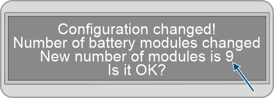
- The battery management system display on the primary battery cabinet shows the number of battery modules detected.
- If the number of battery modules detected does not match the number of battery modules installed, disconnect the battery from the voltage source and check all battery communication connections.
- If the number of battery modules detected is still incorrect after eliminating any battery communication faults, contact Service.
- If the number of battery modules detected matches the number of battery modules installed, confirm the correct number of battery modules. To do this, tap with the fingers on the highlighted area beside the display.
- Activate the next menu item. To do this, tap with the fingers on the highlighted area beside the display.
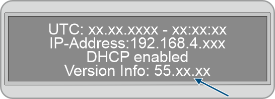
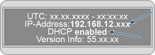
- The battery management system display on the primary battery cabinet shows the installed firmware version and the assigned IP address.
- Ensure that the current firmware version is installed. The firmware version starts with 55.xx.xx.
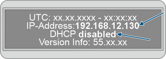
- If the DHCP protocol is disabled on the battery management system and the IP address is specified, set the IP address of the battery management system to 192.168.12.130 during commissioning of the inverter.
- If the DHCP protocol is enabled on the battery management system and the IP address is variable, do not make any changes to the configuration of the battery communication during commissioning of the inverter. The default battery communication settings will be automatically used.
- Activate the next menu item. To do this, tap with the fingers on the highlighted area beside the display.
- The battery management system display on the primary battery cabinet changes from the Status to INIT mode.
- The SWITCH control element flashes.
- Commission the inverter.
- Once commissioning of the inverter is complete, the battery management system display on the primary battery cabinet changes from the Status to PRECH mode. This indicates that precharging mode of the battery has started.
- Precharging mode is complete once the battery management system display on the primary battery cabinet changes from the Status to OK mode. The battery is now ready for operation.
DHCP protocol disabled or enabled
Performing the next step depends on whether the DHCP protocol for the inverter’s battery communication interface is enabled or disabled.
Also see: