
Installing the battery modules
 Qualified person
NOTICE
Potential for damage to sliding rails and cage nuts due to battery modules
The battery modules can knock against sliding rails and cage nuts when inserting the battery modules into the battery cabinet. This can damage the sliding rails. The cage nuts can become loose and fall down.
- Always move the battery modules slowly and carefully when inserting them into the battery cabinet.
NOTICE
Potential for damage to battery modules due to incorrect insertion of battery modules
The weight of a battery module may lead to a mechanical overload of another battery module. This overload will result in damage to the battery module.
- Never rest battery modules on already mounted battery modules during installation.
- Use a suitable lifting aid to mount the battery modules.

Performing system registration
To complete commissioning, a system registration must be performed
- Use the following link for the system registration: https://my.sma-service.com/.
Procedure:
- Record the battery modules’ serial numbers in the commissioning report.
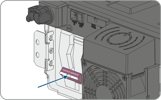
- On each battery module, check whether the shock sensor on the front of the battery module has tripped. Tripping of the shock sensor is indicated by a red color in the indication panel.
- If the shock sensor on a battery module has tripped, document the battery module condition using photographs and contact Service. Do not install the affected battery module.
- Mount only battery modules with a DC output voltage of at least 76.5 V. For this, measure the DC output voltage between -POL and +POL on each battery module.
- If the DC output voltage of a battery module is not above 76.5 V, contact Service.
- If the difference between the lowest and the highest DC output voltage is 200 mV or more, also contact Service.
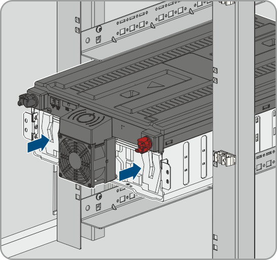
- Determine the lowermost mounting level for inserting the first battery module. Note that the battery modules are mounted one below the other in the battery cabinet. The final battery module is mounted directly under the battery management system.
- Insert the first battery module in the two sliding rails of the lowermost mounting level. Slide in the battery module carefully so the preassembled cage nuts do not become dislodged.
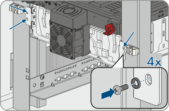
- Fasten the first battery module in place at the preassembled cage nuts (PH2, torque: 3 Nm). Use four of the supplied flat head screws and four of the supplied plastic washers for this.
- On the first battery module, check once again whether the shock sensor on the front of the battery module has tripped. Tripping of the shock sensor is indicated by a red color in the indication panel.
- If the shock sensor on the first battery module has tripped, document the battery module condition using photographs and contact Service. Do not install this battery module.
- Mount the rest of the battery modules, working from the bottom to the top. Proceed as described for the first battery module.
Also see: