
Connect signal cables for backup operation
 Qualified person
If there are multiple inverters in the system but backup loads are only connected to one of them, the backup loads should be connected to the inverter that is configured as the System Manager.
Additionally required material (not included in the scope of delivery):
For secure power supply operation: 1 standard commercial switch
Procedure:
- Connect the connection cable to the switch (see the manual of switch).
- Disconnect the inverter from all voltage sources ( > Check that the inverter is de-energized).
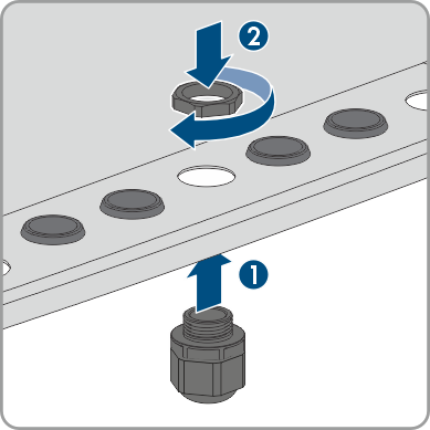
- Remove the filler plug from the enclosure opening for connection to the multifunction relay and the signal cable for backup operation.
- Insert the M32x1.5 cable gland with a four-hole cable support sleeve into the enclosure opening for connection to the multifunction relay and the signal cable for backup operation. Then, tighten it from the inside using the counter nut.
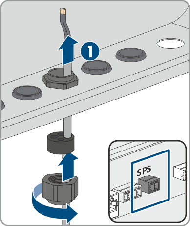
- Unscrew the union nut from the cable gland and lead the cable through.
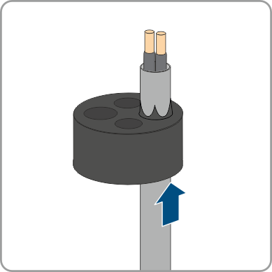
- Remove the four-hole cable support sleeve from the cable gland.
- Insert the cable into a fitting enclosure opening of the four-hole cable support sleeve. In doing so, pierce the closed side of the enclosure opening.
- Press the four-hole cable support sleeve with the cable into the cable gland and route the cable to the SPS slot on the communication assembly.
- Dismantle the cable by 20 mm.
- Strip off the conductor insulation by 6 mm.
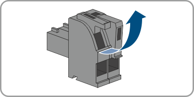
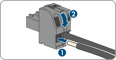
- Release the conductor entries on the supplied two-pole connector.
- Connect the conductors to the supplied 2-pole connector. To do so, plug the conductors into the conductor entries and close the conductor entries. Observe the connector assignment.
- Plug the 2-pole connector into the socket SPS on the communication assembly. Observe the pin assignment.
- Ensure that the connector is securely in place.
- Ensure that all conductors are correctly connected.
- Ensure that the conductors sit securely in the terminal points.
- Tighten the swivel nut on the cable gland hand-tight.
Also see: