
Check that the inverter is de-energized
 Qualified person
Prior to performing any work on the inverter, always disconnect it from all voltage sources as described in this section. Always adhere to the prescribed sequence.
WARNING
Danger to life due to electric shock from destruction of the measuring device due to overvoltage
Overvoltage can damage a measuring device and result in voltage being present in the enclosure of the measuring device. Touching the live enclosure of the measuring device results in death or lethal injuries due to electric shock.
- Only use measuring devices with a measurement ranges designed for the maximum AC and DC voltage of the inverter.
- Only use measuring devices with measurement ranges designed for the maximum DC voltage of the battery.
Requirement:
The enclosure cover must be removed ( > Remove enclosure lid).
Procedure:
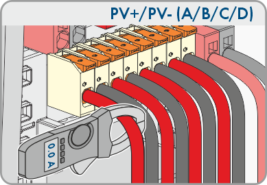
- Use a current clamp to check that no current is present in the DC conductors for the PV modules.
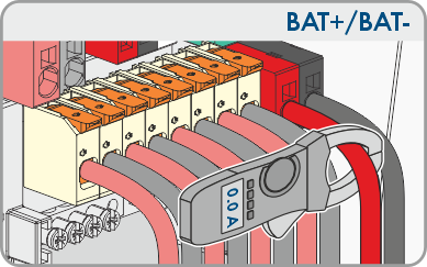
- Use a current clamp to ensure that no current is present in the DC conductors for the battery.
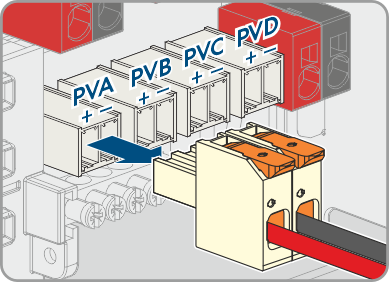
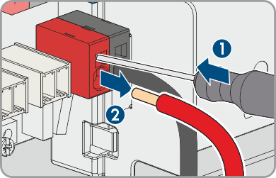
- Write down the positions of the terminal blocks for connecting the PV modules.
- Remove the terminal blocks for connecting the PV modules from the slots.
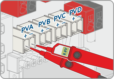
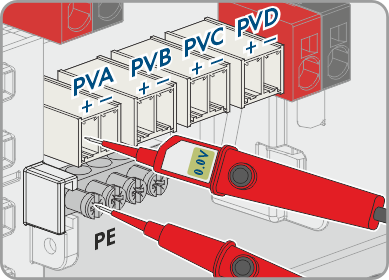
- Use a suitable voltage detector to check that there is no voltage at the PVA, PVB, PVC, and, if applicable, PVD slots between PV+ and PV-.
- At each of the slots PVA, PVB, PVC and, if applicable, PVD, verify the absence of voltage between PV+ and PE on the busbar for grounding the PV modules.
- At each of the slots PVA, PVB, PVC and, if applicable, PVD, verify the absence of voltage between PV- and PE on the busbar for grounding the PV modules.
- Remove the DC conductors for the battery from the terminals.
- Use a suitable voltage detector to ensure that there is no voltage between the connection terminals BAT+ and BAT-.
- Use a suitable voltage detector to ensure that there is no voltage between the connection terminal BAT+ and PE on the busbar for grounding the PV modules.
- Use a suitable voltage detector to ensure that there is no voltage between the connection terminal BAT- and PE on the busbar for grounding the PV modules.
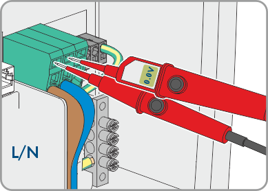
- Ensure that there is no voltage at the AC connection terminals between L1 and N.
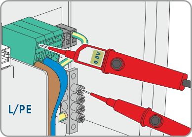
- Ensure that there is no voltage between L on the AC connection terminals and PE on the busbar for grounding the AC connection.
Also see: