
Connecting Signal Source to Digital Input GSI
 Qualified person

Network cable and fast-stop switch use the same cable gland
If a fast-stop switch is to be connected, plug the network cables into the cable support sleeve along with the fast-stop switch connection cable and insert them into the inverter.
Additional required material (not included in the scope of delivery):
1 fast-stop switch (break contact)
Requirements:
The signal source must be technically suitable for connection to the digital inputs ( > Technical Data).
Procedure:
- Disconnect the inverter from all voltage sources ( > Check that the inverter is de-energized).
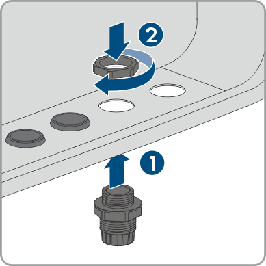
- Remove the filler plug from the enclosure opening for connecting the network cables.
- Insert the M32x1.5 cable gland with four-hole cable support sleeve for communication connections into the enclosure opening for connecting the network cables as well as the fast-stop switch and tighten it from the inside with the counter nut.
- Unscrew the union nut from the cable gland and lead the cable through.
- Remove the four-hole cable support sleeve from the cable gland.
- Insert the cable into a fitting enclosure opening of the four-hole cable support sleeve. In doing so, pierce the closed side of the enclosure opening.
- Press the four-hole cable support sleeve with the cable into the cable gland and route the cable to the GSI slot on the communication assembly.
- Dismantle the cable by 20 mm.
- Strip off the conductor insulation by 6 mm.
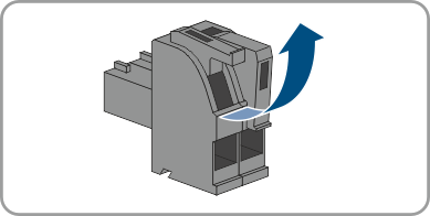
- Remove the plugged two-pole connector with bridge from the GSI socket.
- Remove the bridge from the 2-pole connector.
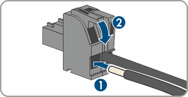
- Release the conductor entries on the 2-pole connector.
- Connect the conductors to the 2-pole connector. To do so, plug the conductors into the conductor entries and close the conductor entries. Observe the connector assignment.
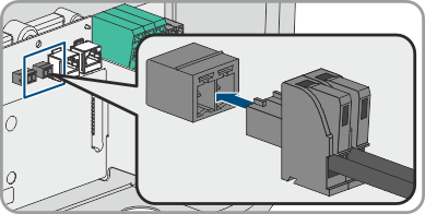
- Plug the two-pole connector with connection cables into the socket GSI on the communication assembly. Observe the pin assignment.
- Ensure that the connector is securely in place.
- Ensure that all conductors are correctly connected.
- Ensure that the conductors sit securely in the terminal points.
- Tighten the swivel nut on the cable gland hand-tight.
Also see: