
Connecting the Utility Grid
 Qualified person
- Disconnect the inverter from all voltage sources ( > Check that the inverter is de-energized).
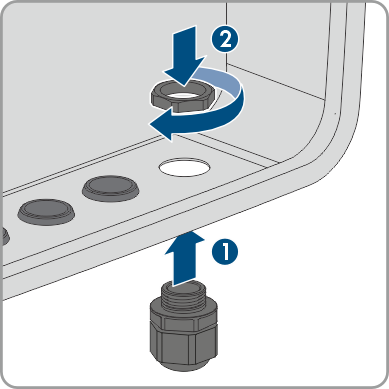
- Remove the filler plug from the enclosure opening for connection to the utility grid.
- Insert the M32x1.5 cable gland with seal insert into the enclosure opening for connecting to the utility grid and tighten it from the inside with the counter nut.
- For cable diameters over 18 mm, remove the seal insert from the cable gland
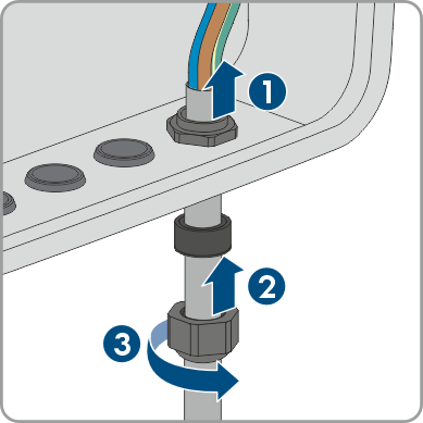
- Feed the cable through the cable gland and the seal insert into the interior of the inverter. If necessary, slightly loosen the swivel nut of the cable gland.
- Dismantle the cable by 100 mm.
- Strip the insulation of L, N and the grounding conductor by 18 mm.
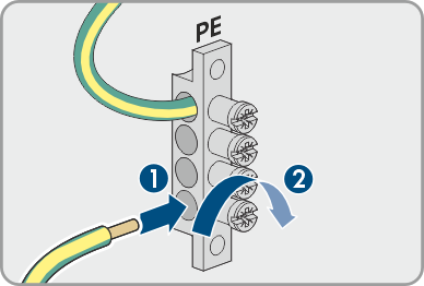
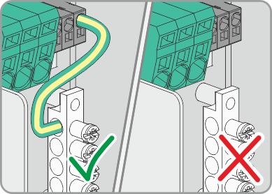
- Connect the PE to the busbar according to the label, as short as possible without the conductor being under tension. To do so, insert the conductor into the busbar against the stop and tighten the screw (PZ2, minimum torque 2.5 Nm).
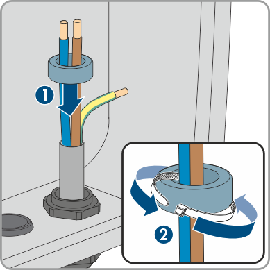
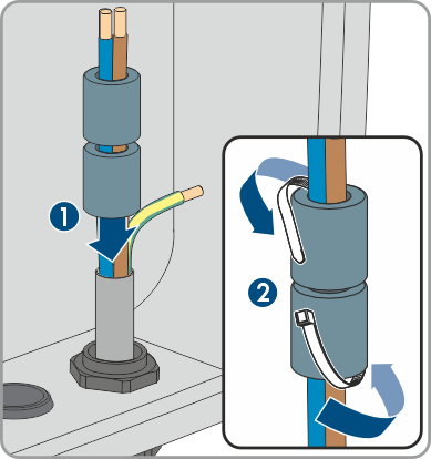
- For SBSE3.6-50 / SBSE4.0-50 / SBSE5.0-50 / SBSE6.0-50: Pass the N and L through the ferrite and secure the ferrite with cable ties.
- For SBSE8.0-50 / SBSE9.9-50: Pass N and L through the two ferrites and secure the ferrites with cable ties.
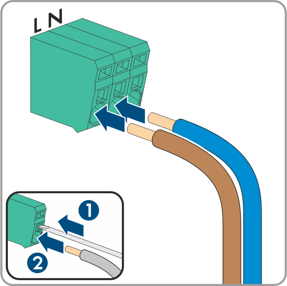
- Connect N and L to the terminal block AC according to labeling. If necessary, open the terminal points with a flat-blade screwdriver (4 mm).
- Make sure that the cable bridge for grounding the N conductor is installed.
- Tug lightly to ensure that all conductors are secured in the terminals.
- Tighten the union nut on the cable gland hand-tight.
CAUTION
Only applies to Australia!
If present, remove the grounding conductor connection between N and the busbar . To do this, unlock the terminal with a flat-blade screwdriver (3.5 mm). Ensure that the socket for the secure power supply operation is grounded externally.
Also see: