
Connecting the Network Cables
 Qualified person
The following action describes how you can connect the inverter to the local network and the SMA Energy Meter or Sunny Home Manager. If there are multiple inverters in the system, the SMA Energy Meter must be connected to the inverter that will be configured as System Manager.
 DANGER
Danger to life due to electric shock in case of overvoltages and if surge protection is missing
Overvoltages (e.g., in the event of a flash of lightning) can be further conducted into the building and to other connected devices in the same network via the network cables or other data cables if there is no surge protection. Touching live parts and cables results in death or lethal injuries due to electric shock.
- Ensure that all devices in the same network and the battery are integrated into the existing surge protection.
- When laying the network cables or other data cables outdoors, it must be ensured that a suitable surge protection device is provided at the transition point of the cable from the product or the battery outdoors to the inside of a building.
- The Ethernet interface of the product is classified as "TNV-1" and offers protection against overvoltages of up to 1.5 kV.

Network cable and fast-stop switch use the same cable gland
If a fast-stop switch is to be connected, plug the network cables into the cable support sleeve along with the fast-stop switch connection cable and insert them into the inverter.
Additionally required material (not included in the scope of delivery):
Network cablesNetwork cable requirements
Where required: Field-assembly RJ45 connector.
Procedure:
- Disconnect the inverter from all voltage sources ( > Check that the inverter is de-energized).
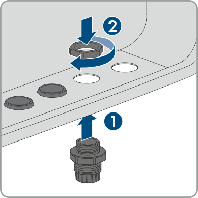
- Remove the filler plug from the enclosure opening for connecting the network cables.
- Insert the M32x1.5 cable gland with four-hole cable support sleeve for communication connections into the enclosure opening for connecting the network cables as well as the fast-stop switch and tighten it from the inside with the counter nut.
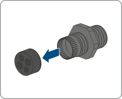
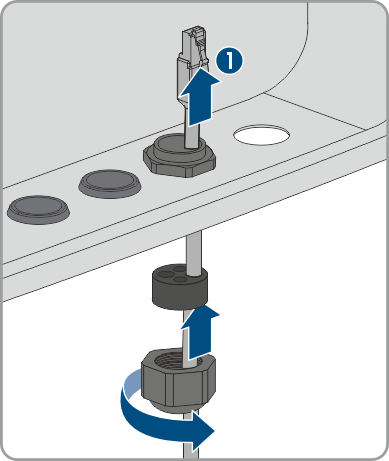
- Unscrew the union nut from the cable gland and run it over each network cable.
- Remove the four-hole cable support sleeve from the cable gland.
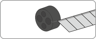
- Use a cutter knife to cut a enclosure opening suitable for each network cable into the four-hole cable support sleeve.
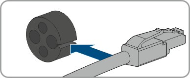
- Insert each network cable into one of the enclosure opening.
- Press the 4-hole cable support sleeve into the cable gland and guide each network cable to the network port.
- When using a self-assembly network cable, assemble the RJ45 connectors and connect them to the network cable (see connector documentation).
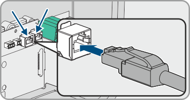
- Insert each network cable into one of the network connectors LAN-1 and LAN-2. Ensure that the network cable cannot touch the AC cables.
- Tug lightly to ensure that the network cable is secure.
- If you would like to integrate the inverter into a local network, connect the other end of a network cable to the local network (e.g., via a router).
- To connect the inverter to an SMA Energy Meter or an SMA Home Manager, connect the other end of the network cable to the SMA Energy Meter or to the Sunny Home Manager. Note that an SMA energy meter must always be connected to the inverter, which is configured as a System Manager.
- Tighten the union nut on the cable gland hand-tight.
Also see: