
Interior View
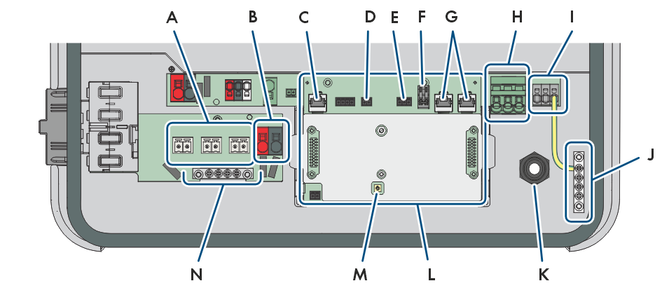
Connection Area of the Inverter
Position | Designation |
|---|---|
A | +PVA-, +PVB-, +PVC- and, depending on the power class,+PVD- terminal blocks for connecting the PV modules |
B | Connection terminals BAT+ and BAT - for connecting the battery power cables |
C | Network connector BATTERY for connecting the battery communication cable |
D | Slot SPS for connecting the signal cable for backup operation |
E | MFR slot for connection to the multifunction relay |
F | Terminal block GSI with inserted bridge for the connection of a fast-stop switch |
G | Network ports LAN-1 and LAN-2 for connecting energy meter, router, battery communication system, communication system for other PV inverters, or other Ethernet-capable devices |
H | Terminal block AC for the connection of L and N of the utility grid |
I | Terminal block SPS for connecting L and N of the signal cable for backup operation |
J | Busbar for grounding of AC connections |
K | Cable gland M20x1.5 for connection of power cable for backup operation |
L | Communication assembly |
M | Wi-Fi antenna socket |
N | Grounding busbar for connection of additional grounding (if necessary) |