
Design of the Indoor Version of the Battery Cabinet
Design of the Indoor Version of the Battery Cabinet
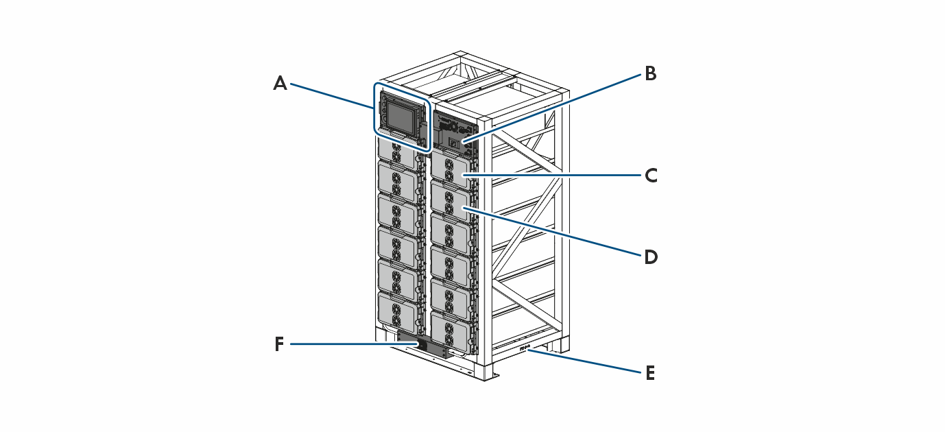
Position | Designation |
|---|---|
A | Control panel (LCU = Local Control Unit) surrounded by the following control elements:
Connections for the AC cable for the electricity supply and for CAN communication to the inverter are positioned behind the control panel. |
B | High-voltage box (including Battery Management System)
|
C | Cover without battery module Depending on the order option, a few compartments may be empty. Empty compartments are only equipped with a cover. |
D | Battery module |
E | Grounding points on the left-and right-hand sides |
F | DC circuit breaker |