
Setting Time-Dependent One-Level Load Shedding
The basic procedure for changing operating parameters is explained in another section ( > Changing Operating Parameters).
The time-dependent load shedding divides the day into two intervals ( > Setting Time-Dependent Functions). You set the SOC thresholds that apply for each interval. For example, you can set that no loads are to be disconnected from the utility grid during the night where possible.
Significance of the SOC thresholds:
When the state of charge of the battery reaches the lower SOC threshold, the multifunction relay opens the connected load-shedding contactor. The load-shedding contactor disconnects the loads from the utility grid. When the state of charge of the battery reaches the upper SOC threshold during recharging, the multifunction relay closes the connected load-shedding contactor. The load-shedding contactor connects the loads to the utility grid.
| From 10:00 p.m. to 6:00 a.m., the load-shedding contactor is not to disconnect the loads from the utility grid where possible. |

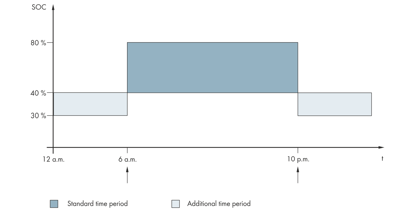
Profile of the SOC thresholds for controlling the load-shedding contactor and the start times for the intervals
The start time for the first interval is set to 6:00 a.m. The lower SOC threshold is set to 40% and the upper SOC threshold is set to 80% in this time interval.
The start time for the second interval is set to 10:00 p.m. The lower SOC threshold is set to 30% and the upper SOC threshold is set to 40% in this time interval.
Procedure:
- Select Device > Load shedding 1 > Additional time range.
- Set the parameters for the standard time period:
Set the parameter Time load shedding 1 to the start time for the standard time period.
Set the parameter Lmt value battery state of charge for start load shedding 1 to the lower SOC threshold for the standard time period.
Set the parameter Lmt value battery state of charge for stop load shedding 1 to the upper SOC threshold for the standard time period.
- Set the parameters for the additional time period:
Set the parameter Start time additional time range load shedding 1 to the start time for the additional time period.
Set the parameter Limit battery state of charge for start load shedding 1 in add time range to the lower SOC threshold for the additional time period.
Set the parameter Limit battery state of charge for stop load shedding 1 in add time range to the upper SOC threshold for the additional time period.
- Ensure that the parameter of the multifunction relay is set to 1-stage load shedding or 1st stage with 2-stage load shedding ( > Setting the Functions of the Multifunction Relays).