
Connecting Relay 1 and Relay 2
 Qualified person
If you are using a multifunction relay, always connect it as follows:

Switching Behavior of the Slaves
In case of a fault, the multifunction relays of the slaves switch less reliably than the multifunction relays of the masters. In case of a fault, the slaves wait for the master to confirm the fault.
Additionally required material (not included in the scope of delivery):
- Suitable bootlace ferrules if using stranded wire
Requirements:
- The technical requirements of the multifunction relay must be met ( > Technical Data).
Cable requirements:
- Copper wire
- Conductor cross-section: 0.2 mm² to 2.5 mm²
Procedure:
- Break through a suitable location in the cable feed-through plate with a sharp object.
- Strip 7 mm of the cable insulation.
- Lead the cable through the hole in the cable feed-through plate into the Sunny Island.
- When connecting cables to Relay 1 and Relay 2, always insert a silicone tube.
- Always connect the cables to Relay 1 and Relay 2 as described in the following.
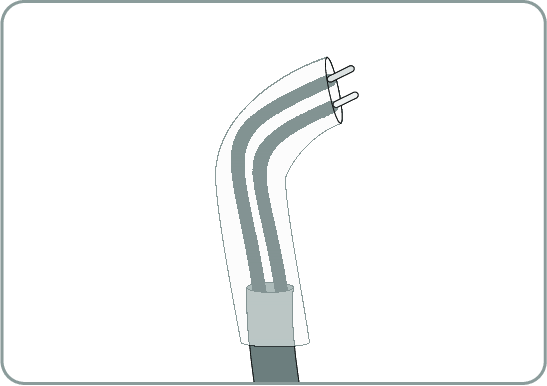
- Cut a silicon tube to the length of the cable in the Sunny Island.
- Pull the silicone tube over the cable. In this way, the cable is double-insulated.
- Lead the cable into the Sunny Island making sure that it does not touch any data cables.
- Connect the insulated conductors to the 3-pole terminal blocks included in the scope of delivery (torque: 0.5 Nm to 0.6 Nm, blade width: 1 mm). Observe the correct assignment of the connections when doing so.
- Ensure that the conductors are plugged completely into the terminals up to the insulation.
- In accordance with the labeling, plug the 3-pole terminal block into the connection Relay1 or Relay2 on the inverter until the terminal block audibly snaps into place.
WARNING
Danger to life from electric shock due to incorrect insulation
In the case of faulty insulation, supposedly de-energized parts or cables may be live. Touching live components or cables can result in death or serious injury due to electric shock.
Connection | Explanation |
|---|---|
NC | Closed when idle |
C | Change-over contact |
NO | Open when idle |