
Connecting contact for fast stop to digital input
 Qualified person
You can connect a contact for the fast stop switch at the digital inputs DI1+ and DI1- of the terminal block LOCAL STOP. The inputs are provided twice and allow the parallel connection of several inverters ( > Fast stop circuitry overview). To guarantee a reliable function through parallel connection of several devices, only inverters of the same type may be used.
Additionally required material (not included in the scope of delivery):
External disconnecting device with potential-free contact to trigger the fast stop function
Procedure:
- Connect the connection cable to the contact for the fast stop (see the manual from manufacturer).
- Disconnect the inverter from all voltage sources ( > Disconnecting the product from voltage sources).
- Open the cable compartment ( > Opening the Cable Compartment).
- Strip off 7 mm of the conductor insulation from each of the connection cable conductors.
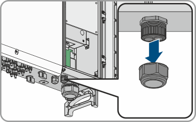
- Remove the swivel nut from an unused cable gland for communication cables.
- Thread the swivel nut over the connection cable.
- Remove the two-hole cable support sleeve from the cable gland. As required, use the cable support sleeve for a cable diameter of between 4.5 mm to 6 mm or between 6 mm to 8 mm that is included in the scope of delivery.
- Remove the sealing plug from one of the enclosure openings of the two-hole cable support sleeve and insert the connection cable into the enclosure opening.
- Press the two-hole cable support sleeve with the cable into the cable gland and route the connection cable to the COM assembly at the bottom of the cable compartment. Ensure that any unused enclosure openings of the two-hole cable support sleeve are sealed with sealing plugs.
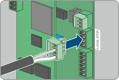
- Remove the terminal block LOCAL STOP from the COM assembly.
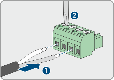
- Insert the stripped conductors up to the stop into the clamping points DI+ and DI- and fasten with a flat-blade screwdriver (torque: 0.2 Nm).
- Ensure that the conductors are plugged into the terminal points tightly by pulling slightly on the conductors.
- Plug the terminal block onto the COM assembly according to the labeling LOCAL STOP.
- Tighten the swivel nut on the cable gland hand-tight. This will secure the connection cable in place.
- Configure the fast stop function ( > Activating the Fast Stop Function).
Also see: