Connecting the Network Cables
 Qualified person
 DANGER
Danger to life due to electric shock in case of overvoltages and if surge protection is missing
Overvoltages (e.g., in the event of a flash of lightning) can be further conducted into the building and to other connected devices in the same network via the network cables or other data cables if there is no surge protection. Touching live parts and cables results in death or lethal injuries due to electric shock.
- Ensure that all devices in the same network are integrated in the existing overvoltage protection.
- When laying the network cable outdoors, ensure that there is suitable surge protection at the network cable transition from the product outdoors to the network inside the building.
- The Ethernet interface of the product is classified as "TNV-1" and offers protection against overvoltages of up to 1.5 kV.
Additionally required material (not included in the scope of delivery):
1 network cable
Network cable requirements:
The cable length and quality affect the quality of the signal. Observe the following cable requirements:
Cable type: 100BaseTx
Cable category: minimum Cat6
Plug type: RJ45 of Cat6 or higher
Shielding: S/UTP, F/UTP or higher
Number of insulated conductor pairs and insulated conductor cross-section: at least 2 x 2 x 0.22 mm²
Maximum cable length between two nodes when using patch cables: 50 m
Maximum cable length between two nodes when using installation cables: 100 m
UV-resistant if installed outdoors.
Router requirements:
DHCP support via the Internet router, with MAC binding is recommended. If DHCP is not supported, an IP address from the address range of the router must be assigned manually to each device.
Fast Ethernet with 100 Mbit/s data transfer rate
Procedure:
- Disconnect the product from voltage sources ( > Disconnecting the product from voltage sources).
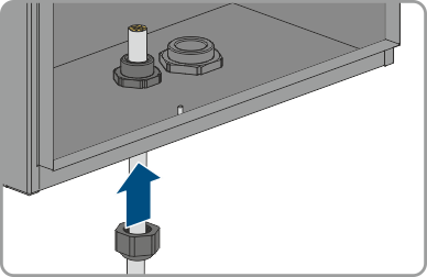
- Guide the network cable through the cable gland and into the product. To do so, slightly loosen the union nut (M20).
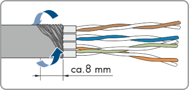
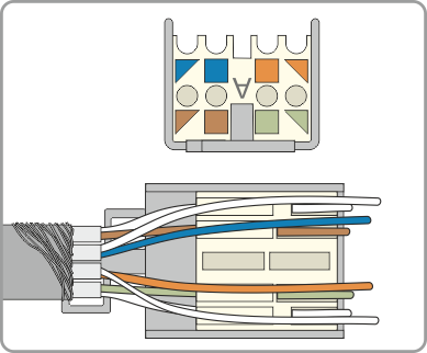
- Strip off the insulation from the network cable (min. 40 mm) and shorten the braided shield to approx. 20 mm.
- Fold the braided shield downward and shorten the shielding to 5 mm.
- Evenly wrap the braided shield around the cable sheath to approx. 8 mm.
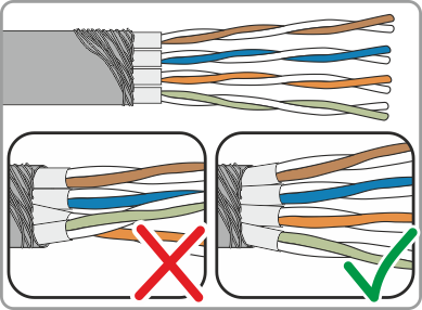
- Sort the insulated conductors into pairs, making sure that they do not cross each other.
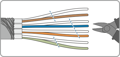
- Trim the insulated conductor pairs at an angle.
- Place the insulated conductor pairs in the module.
- Make sure that the insulated conductors protrude by a maximum of 0.5 mm. Secure the supplied cable tie for strain relief and cut off the end.
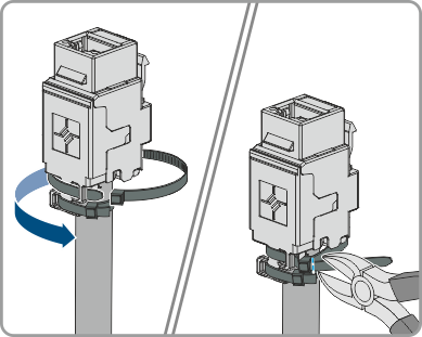
- Press the two module pieces together with the help of pliers.
- Secure the second supplied cable tie and cut off the end.
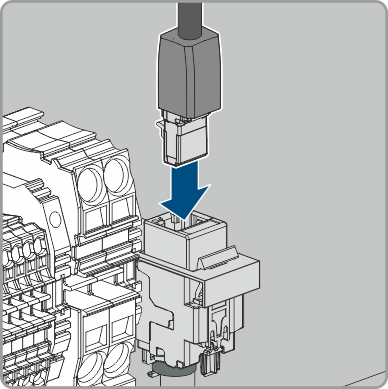
- Clamp the RJ45 module in the holder.
- Connect the network cable of the charge controller to the RJ45 module.
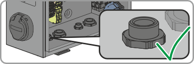
- Tighten the union nut on the cable gland hand-tight.
- Close unused enclosure openings and the pressure-equalizing membrane.