Mounting the charging stand
 CAUTION
Risk of injury due to weight of product
Injuries may result if the product is lifted incorrectly or dropped while being transported or mounted.
- Wear suitable personal protective equipment for all work on the product.

For a concrete foundation produced by the operator, billing, design and production are exclusively the responsibility of the operator or the company that carried out mounting on behalf of the operator.
Procedure:
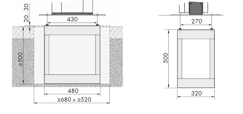
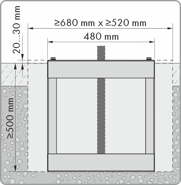
Dimensions of the foundation hole (Dimensions in mm)
- Ensure that the AC cable is long enough to connect to the product.
- Excavate the foundation hole with the following dimensions: width ≥680 mm x height ≥500 mm x depth ≥520 mm.
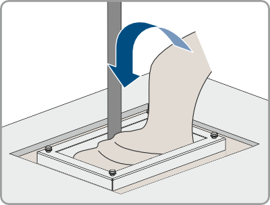
- Insert the embedded section of the column into the hole and guide the AC cable upwards.
- Stabilize the embedded section of the column using class C30/37 concrete.
- Let the concrete completely cure before starting to assemble the column.
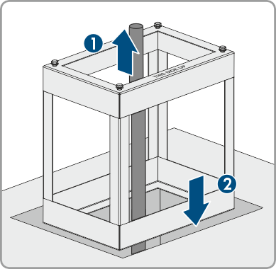
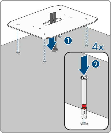
- First remove the 4 screws (M10x20) and the 4 washers (M10) from the embedded section.
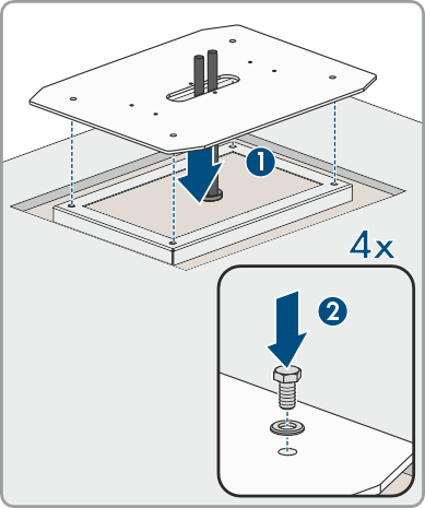
Then position the base plate on the 4 holes of the embedded section of the column. Secure the base plate with the 4 screws (M10x20) and the 4 (M10) washers (AF16). - Optional: You can also directly fasten the base plate to a suitable support surface. To do so, drill 4 holes and secure the base plate using 4 heavy-duty anchors (M10x108, not in the scope of delivery) (AF16).
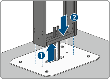
- When putting on the middle section, guide the AC cable through the middle section of the column. Position the middle section on the 6 holes in the base plate. Pay attention to the weight.
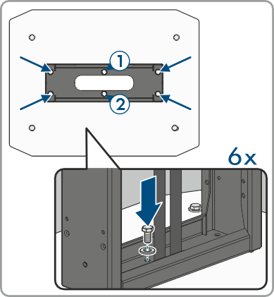
- Use the 6 screws (M8x10) and washers to secure the middle section of the column (AF13, tightening torque: 25 Nm). First secure the two screws at the center of the middle section.
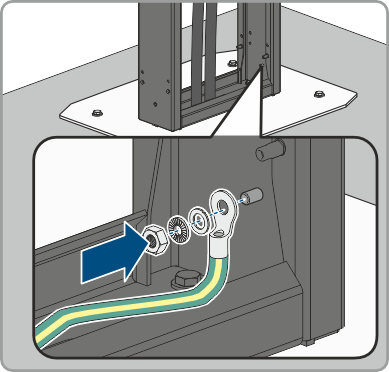
- Additional ground: Connect the grounding conductor to the grounding bolts of the column. Secure the crimped terminal lug to the grounding bolts. To do so, use the washer (M6), serrated lock washer (M6) and nut (M6) in the scope of delivery of the column.
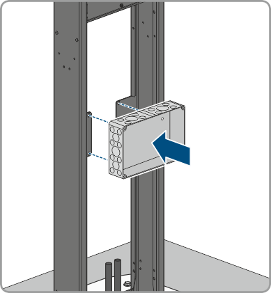
- Optional: You can position an empty enclosure (not in the scope of delivery) on the middle section of the column (width 254 mm x height 180 mm x depth 84 mm).
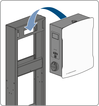
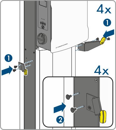
- Hook the product onto the column.
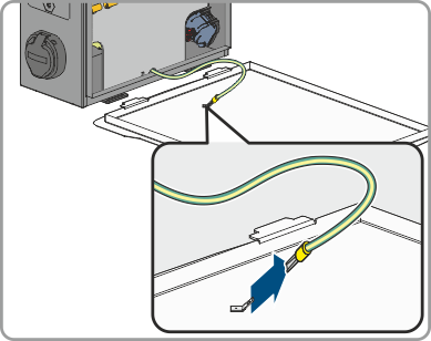
- Use the product key to open the enclosure cover.
- Pull off the grounding cable at the cover.
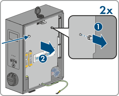
- Remove the safety cover. To do so, loosen the 2 nuts. For the products EVCB-LB-3AC-ECC-10 and EVCB-3AC-ECC-10, safety seals are on the 2 nuts.
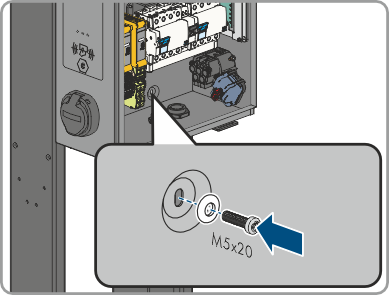
- Secure the product using the sealing washer (M6) (included in the product's scope of delivery) and the screw (M5x20) (included in the scope of delivery of the column) (TX25, tightening torque: 5 Nm).
- Ensure that the product is securely in place.
- Connect to the utility grid ( > Connecting the Utility Grid).
- Connect the network cable ( > Connecting the Network Cables).
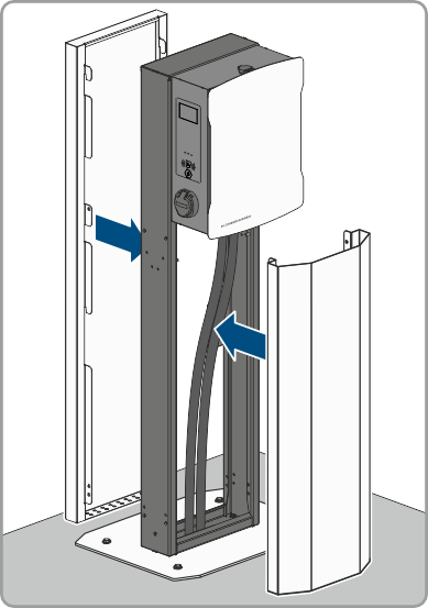
- Hook the cover at the front and rear of the middle section of the column. In the middle section of the column, there are two carrier pins onto which the covers must be hooked.
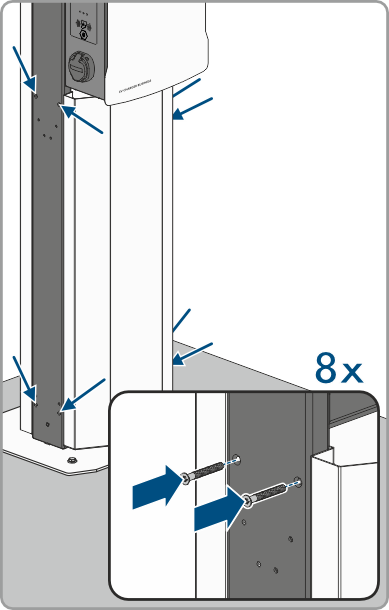
- Secure the two covers to the front and rear with the 8 screws (M5x40) in the scope of delivery of the column (TX25, tightening torque: 5 Nm).
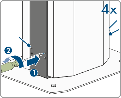
- Lock the covers. To do so, insert a screwdriver through the opening and rotate the set screw counterclockwise until the stop (TX25, tightening torque: 5 Nm). Repeat the procedure at the remaining 3 positions.
- Depending on the product version, secure the cable holder to the side of the column (M6x10). Seal all unused openings with the fir tree clips.