Connecting the Multifunction Relay
The multifunction relay of the inverter is designed as a potential-free change-over contact (NO / NC / COM). Various status messages can be displayed depending on the configuration of the operating mode Operating Modes of the Multifunction Relay.
Cable requirements:
The cable type and cable-laying method must be appropriate for the application and location.
Procedure:
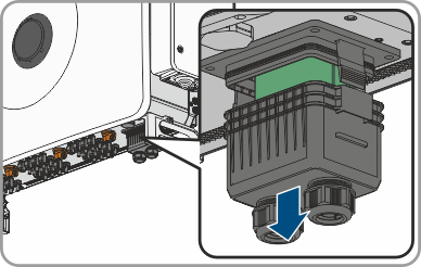
- Remove the cover from the communication connection area.
- Remove the swivel nut from one of the cable glands for the communication cable.
- Thread the swivel nut over the cable.
- Remove the two-hole cable support sleeve from the cable gland. As required, use the cable support sleeve for a cable diameter of between 4.5 mm to 6 mm or between 6 mm to 8 mm that is included in the scope of delivery.
- Remove the sealing plug from one of the enclosure openings of the two-hole cable support sleeve and insert the cable into the enclosure opening.
- Strip off a maximum of 6 mm of the cable insulation.
- Unlock the conductor inserts on the provided 3-pole connector by loosening the screw.
- Connect the conductors of the connection cable to the supplied 3-pole connector. To do so, plug the conductors into the conductor entries and close the conductor entries by tightening the screws. Observe the connector assignment.
- Plug the 3-pole connector into the socket D0: COM, NC, NO on the product. Observe the pin assignment.
- Ensure that the connector is securely in place.
- Ensure that all conductors are correctly connected.
- Ensure that the conductors sit securely in the terminal points.
- Tighten the swivel nut on the cable gland hand-tight.