
Connecting contact for fast stop to digital input
 Qualified person

Observe pin assignment for grid and PV system protection
Note that when connecting the grid and PV system protection required by VDE-AR-N-4105, the connection must be made to the pin with the FS1 assignment. The pin with the FS2 assignment is considered a universal connection and is unsuitable for implementing grid and PV system protection. It is used for the connection of an external switch, for example.
The inputs are provided twice and allow the parallel connection of several inverters. To guarantee a reliable function through parallel connection of several devices, only inverters of the same type may be used.
Additional required material (not included in the scope of delivery):
External disconnecting device with potential-free contact to trigger the fast stop function
Procedure:
- Connect the connection cable to the contact for the fast stop (see the manual from manufacturer).
- Disconnect the inverter from voltage sources and secure it against being switched on again ( > Disconnecting the Inverter from Voltage Sources).
- Open the cable compartment ( > Opening the Cable Compartment).
- Strip off 7 mm of the conductor insulation from each of the connection cable conductors.
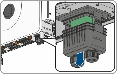
- Remove the cover from the communication connection area.
- Remove the swivel nut from an unused cable gland for communication cables.
- Thread the swivel nut over the connection cable.
- Remove the two-hole cable support sleeve from the cable gland. As required, use the cable support sleeve for a cable diameter of between 4.5 mm to 6 mm or between 6 mm to 8 mm that is included in the scope of delivery.
- Remove the sealing plug from one of the enclosure openings of the two-hole cable support sleeve and insert the connection cable into the enclosure opening. Ensure that the connection cable is located about 15 cm within the cover so as not to damage the cable connection when pulling off the cover.
- Press the two-hole cable support sleeve with the cable into the cable gland and route the connection cable to the COM assembly at the bottom of the cable compartment. Ensure that any unused enclosure openings of the two-hole cable support sleeve are sealed with sealing plugs.
- Remove the terminal block incl. connection area FS from the COM assembly.
- Insert the stripped conductors up to the stop into the terminal points FS1 or FS2 and Vcc and fasten with a flat-blade screwdriver (tightening torque: 0.2 Nm).
- Ensure that the conductors are plugged into the terminal points tightly by pulling slightly on the conductors.
- Plug the terminal block onto the COM assembly according to labeling.
- Tighten the swivel nut on the cable gland hand-tight. This will secure the connection cable in place.
- For the fast stop connection: configure function Activating the fast stop function.
- For the grid and PV system protection connection: configure function ( > Configuring the fast stop for the external grid and PV system protection function).
Also see: