Assembling the DC Connectors
 Qualified person
For connection to the inverter, all PV module connection cables must be fitted with the DC connectors provided. Assemble the DC connectors as described in the following. The procedure is identical for both connectors (+ and -). The graphics for the procedure are shown for only the positive connector as an example. Pay attention to the correct polarity when assembling the DC connectors. The DC connectors are marked with the symbols "+" and "-".
 DANGER
Danger to life due to electric shock when live components or DC cables are touched
When exposed to light, the PV modules generate high DC voltage which is present in the DC cables. Touching live DC cables results in death or lethal injuries due to electric shock.
- Do not touch non-insulated parts or cables.
- Disconnect the product from voltage sources and ensure it cannot be reconnected before working on the device.
- Do not disconnect the DC connectors under load.
- Wear suitable personal protective equipment for all work on the product.
NOTICE
Destruction of the inverter due to overvoltage
If the open-circuit voltage of the PV modules exceeds the maximum input voltage of the inverter, the inverter can be destroyed due to overvoltage.
- If the open-circuit voltage of the PV modules exceeds the maximum input voltage of the inverter, do not connect any strings to the inverter and check the design of the PV system.
Procedure:
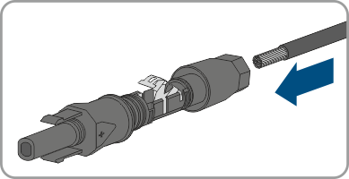
- Strip approx. 15 mm of the cable insulation.
- Insert the stripped cable into the DC connector up to the stop. When doing so, ensure that the stripped cable and the DC connector are of the same polarity.
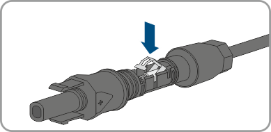
- Press the clamping bracket down until it audibly snaps into place.
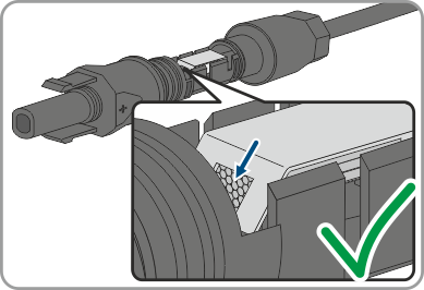
- The stranded wire can be seen inside the clamping bracket chamber.
- If the stranded wire is not visible in the chamber, the cable is not correctly inserted and the connector must be reassembled. To do this, the cable must be removed from the connector.
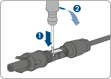
- To take out the cable, loosen the clamping bracket. To do so, insert a screwdriver (blade width: 3.5 mm) into the clamping bracket and pry the clamping bracket open.
- Remove the cable and go back to step 2.
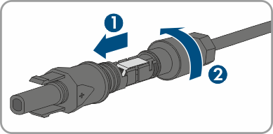
- Push the swivel nut up to the thread and tighten (torque: 2 Nm).