
Disconnecting the Terminals from the Inverter
 Qualified person
To decommission the inverter completely upon completion of its service life, proceed as described in this Section. If the inverter is defective and you have received a replacement device, observe the information on ( > Replacing the Product with a Replacement Device).
Procedure:
- Disconnect the inverter from all voltage sources ( > Disconnecting the Inverter from Voltage Sources).
- Wait 30 minutes for the enclosure to cool down.
- Unscrew the swivel nut from the threaded sleeve for the network cable.
- Unscrew and remove the threaded sleeve from the network port thread on the inverter.
- Release the network cable plug and pull it out of the jack on the inverter.
- Take the cable support sleeve out of the threaded sleeve and remove the network cable from the cable support sleeve.
- Lead the network cable out of the threaded sleeve and the swivel nut.
- Put the protective cap on the network port.
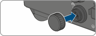
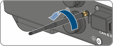
- Unscrew and remove the antenna.
- If there is a protective cap available, plug the protective cap onto the jack for connecting the antenna.
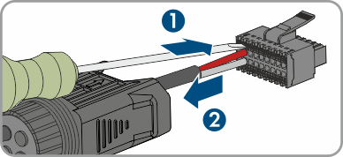
- Remove connector from COM socket.
- Remove the swivel nut from the threaded sleeve.
- Remove the terminal from the threaded sleeve.
- Remove all conductors from the terminal points using a screwdriver (blade width: 2.5 mm).
- Put the protective cap on the socket.
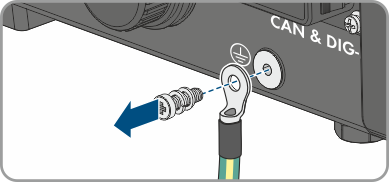
- Remove the AC grounding conductor and, if present, the grounding cable of the PV array frame. For this purpose, unscrew the pan head screw M5x12 (PH2) at each connection point and remove the grounding cable.
CAUTION
Risk of burns due to hot enclosure parts


Also see: