
Check the PV system via insulation resistance measurement for ground faults
 Qualified person
If the voltage measurement does not provide sufficient evidence of a ground fault, the insulation resistance measurement can provide more exact results.
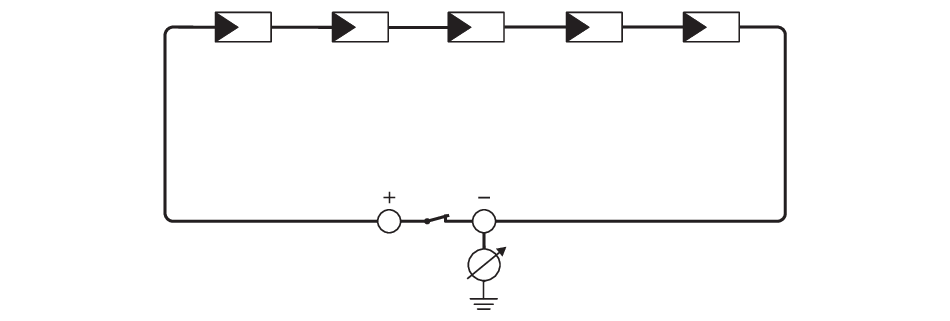
Schematic diagram of the measurement
Required devices:
Suitable device for safe disconnection and short-circuiting
Measuring device for insulation resistance

Device required for safe disconnection and short-circuiting of the PV modules
The insulation resistance can only be measured with a suitable device for safe disconnection and short-circuiting of the PV modules. If no suitable device is available, the insulation measurement must not be carried out.
Procedure:
- Calculate the expected insulation resistance per string.
- Disconnect the inverter from all voltage sources.
- Install the short circuit device.
- Connect the measuring device for insulation resistance.
- Short-circuit the first string.
- Set the test voltage. The test voltage should be as close as possible to the maximum system voltage of the PV modules but must not exceed it (see datasheet of the PV modules).
- Measure the insulation resistance.
- Eliminate the short circuit.
- Measure the remaining strings in the same manner.
- If the insulation resistance of a string deviates considerably from the theoretically calculated value, there is a ground fault present in that string.
- Reconnect to the inverter only those strings from which the ground fault has been eliminated.
- Reconnect all other strings to the inverter.
- Recommission the inverter.
- If the inverter still displays an insulation error, contact the Service. The PV modules might not be suitable for the inverter in the present quantity.
 DANGER
Danger to life due to high voltages
Also see: