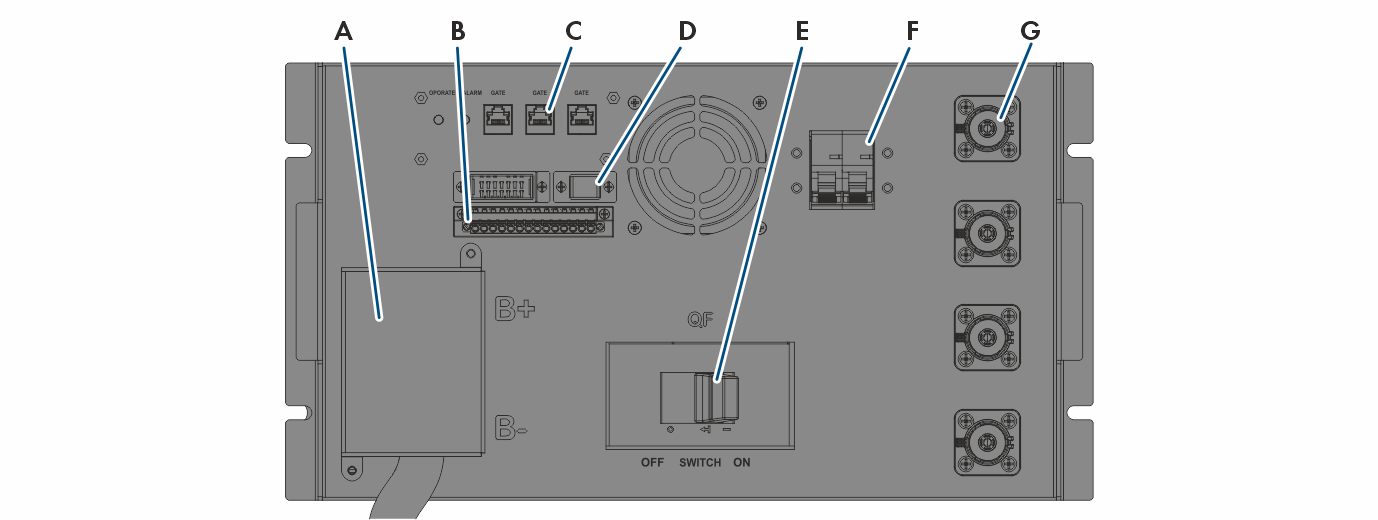
Connection Area of the High-Voltage Box

15982843916

Connections on the high-voltage box

Position

Designation

A

B -: DC connection of the battery modules, negative pole (black)

B +:DC connection of the battery modules, positive pole (red)

B

no function

C

Outdoor version: no function

Indoor version:

  • COM0, LAN: no function

  • COM1: A terminator is preinstalled. If there are at least two secondary battery cabinets, the terminator on the first and second secondary battery cabinets must be replaced by a CAN connection.

  • The CAN communication between multiple battery cabinets is connected in part behind the control panel (COM2).

  • The CAN communication to the inverter is connected behind the control panel (INV).

D

no function

E

QF: High-voltage box ON/OFF switch

F

QFx: Circuit breaker

G

Indoor version:

  • P1 +: DC connection to the inverter or to the DC Combiner Box for the positive pole (red)

  • P1 -: DC connection to the inverter or to the DC Combiner Box for the negative pole (black)

Outdoor version: Not relevant for the installation