
Connecting the CAN communication between the battery cabinets of the indoor version
 Qualified person
One inverter can have up to four battery cabinets connected to it. For systems with more than one battery cabinet, the battery cabinets must be connected to each other in series via a CAN communication bus.
Procedure:
- Check that the preinstalled terminator is plugged into COM1 on the primary battery cabinet.
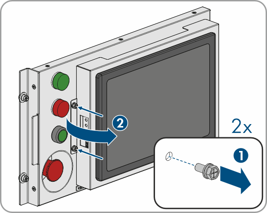
- To access the connections behind the control panel in the following steps, loosen the two screws on the respective control panel and swing open the display to the right.
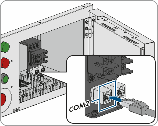
- Connect the primary battery cabinet and the first secondary battery cabinet via the COM2 terminal behind the control panel using a communication cable.
- Connect the first and second secondary battery cabinets via the COM1 terminal on the high-voltage box using a communication cable ( > Connection Area of the High-Voltage Box). Remove the terminators present.
- Connect the second and third secondary battery cabinet via the COM2 terminal behind the control panel using a communication cable.
- Plug a terminator into the last secondary battery cabinet.
- With two secondary battery cabinets: Terminator in COM2 behind the control panel.
- With one or three secondary battery cabinets: Terminator in COM1 on the high-voltage box.
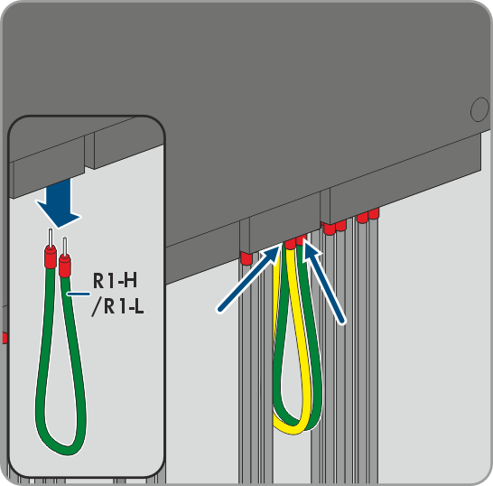
- Disconnect the insulated conductors R1-H and R1-L behind the display of each battery cabinet and remove the cable.
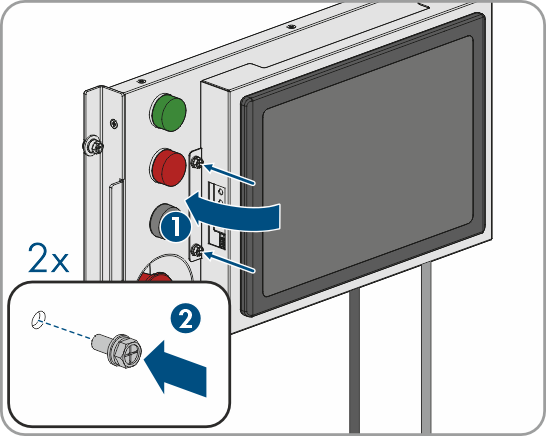
- Close the open displays. When doing so, make sure that the cables are in the slot on the display and are not pinched. Lay the communication cables separately from the DC lines.
- Attach the displays using 2 screws for each (tightening torque: 2.5 Nm).
Also see: