Decommissioning the Inverter
 Qualified person
To decommission the inverter completely upon completion of its service life, proceed as described in this Section. If the inverter is defective and you have received a replacement device, observe the information on how to proceed when receiving a replacement device ( > Procedure for Receiving a Replacement Device).
CAUTION
Risk of injury due to weight of product
Injuries may result if the product is lifted incorrectly or dropped while being transported or mounted.
- Transport and lift the product carefully. Take the weight of the product into account.
- Always have two persons mount and disassemble the product.
- Wear suitable personal protective equipment for all work on the product.
Procedure:
- Disconnect the inverter from all voltage sources ( > Disconnecting the Inverter from Voltage Sources).
- Wait 30 minutes for the enclosure to cool down.
- Unscrew the swivel nut from the threaded sleeve for the network cable.
- Unscrew and remove the threaded sleeve from the network port thread on the inverter.
- Release the network cable plug and pull it out of the jack on the inverter.
- Take the cable support sleeve out of the threaded sleeve and remove the network cable from the cable support sleeve.
- Lead the network cable out of the threaded sleeve and the swivel nut.
- Put the protective cap on the network port.
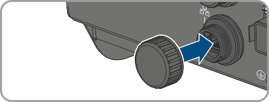
- Unscrew and remove the antenna.
- If there is a protective cap available, plug the protective cap onto the jack for connecting the antenna.
- Remove connector from COM socket.
- Remove the swivel nut from the threaded sleeve.
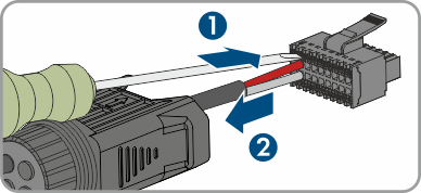
- Remove the terminal from the threaded sleeve.
- Remove all conductors from the terminal points using a screwdriver (blade width: 2.5 mm).
- Put the protective cap on the socket.
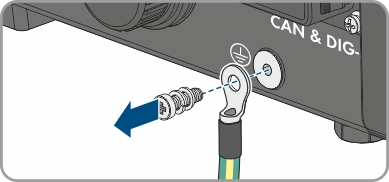
- If an additional grounding or an equipotential bonding is connected to the inverter, unscrew the pan head screw M5x12 (TX25) and remove the grounding cable.
- Unscrew the left- and right-hand pan head screws M4x14 used to secure the inverter to the wall mounting bracket (PH2).
- If the protective cover for the connection area is still in place, reattach the protective cover to the inverter. Otherwise, protect the connection area with another sturdy cover.
- Remove the inverter by lifting it vertically up and off the wall mounting bracket.
- Unscrew the screws for fastening the wall mounting bracket and remove the wall mounting bracket.
- If the inverter is to be stored or shipped, pack the inverter, the AC connectors, the DC connectors, the antenna, the RJ45 protective sleeve, the battery connection cables, the connector for connecting the battery communication and the digital inputs and outputs, and the wall bracket. Use the original packaging or packaging that is suitable for the weight and dimensions of the inverter.
- Dispose of the inverter in accordance with the locally applicable disposal regulations for electronic waste.