Disconnecting the Inverter from Voltage Sources
 Qualified person
Prior to performing any work on the product, always disconnect it from all voltage sources as described in this section. Always adhere to the prescribed sequence.
WARNING
Danger to life due to electric shock from destruction of the measuring device due to overvoltage
Overvoltage can damage a measuring device and result in voltage being present in the enclosure of the measuring device. Touching the live enclosure of the measuring device results in death or lethal injuries due to electric shock.
- Only use measuring devices with a DC input voltage range of 1000 V or higher.
Procedure:
- Disconnect the AC and backup miniature circuit breaker from all 3 line conductors and secure against reconnection.
- Set the DC load-break switch of the inverter to O.
- Switch off the battery or the load-break switch of the battery (see documentation of the battery manufacturer).
- Wait until the LEDs have gone out.
- Wait 10 minutes. This will ensure that the capacitors are discharged.
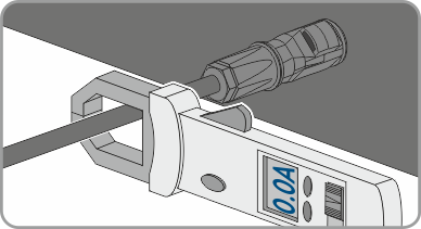
- Use a current clamp to ensure that no current is present in the DC cables.
- Wear insulated gloves and use insulated tools when working on the DC connectors.
- Ensure that the DC connectors are in perfect condition and that none of the DC conductors or DC plug contacts are exposed.
- Carefully release and remove the DC connectors as described in the following.
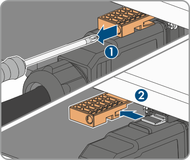
- Release and remove the DC connectors. To do so, insert a flat-blade screwdriver or an angled screwdriver (blade width: 3.5 mm) into one of the side slots and pull the DC connectors out. When doing so, do not lever the DC connectors out, but insert the tool into one of the side slots only to release the locking mechanism, and do not pull on the cable.
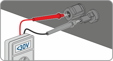
- Ensure that no voltage is present between the positive terminal and negative terminal at the DC inputs using a suitable measuring device.
- Ensure that no voltage is present between the positive terminal and ground as well as between the negative terminal and ground on the DC inputs using a suitable measuring device.
- Ensure that no electric currents are present between the positive terminal and negative terminal at the battery inputs using a suitable measuring device.
- Insert an MC4 wrench (not included in the scope of delivery) into the notch of the DC connectors of the battery connection cables and pull slightly to remove the DC connectors.
- If AC backup loads are connected, ensure that the AC connectors for connection to the utility grid and for connection of the AC backup loads are marked so that they cannot be reversed when reconnected.
- Remove the screw of the fuse terminal of the AC connector for connecting the AC backup loads (PH1) and slide the fuse terminal to the left.
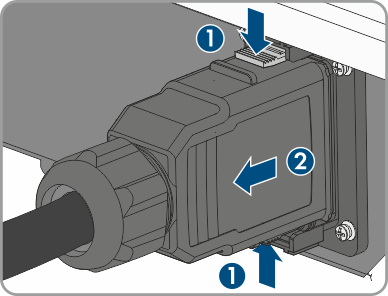
- Squeeze the brackets on the top and bottom of the AC connector for connecting the AC backup loads and apply slight pressure. Pull the AC connector at the same time to remove the AC connector.
- Remove the screw of the fuse terminal of the AC connector for connecting the utility grid (PH1) and slide the fuse terminal to the left.
- Squeeze the tabs on the top and bottom of the AC connector for connecting the utility grid and apply slight pressure. Pull the AC connector at the same time to remove the AC connector.

 DANGER
Danger to life due to electric shock when touching exposed DC conductors or DC plug contacts if the DC connectors are damaged or loose
The DC connectors can break or become damaged, become free of the DC cables, or no longer be connected correctly if the DC connectors are released and disconnected incorrectly. This can result in the DC conductors or DC plug contacts being exposed. Touching live DC conductors or DC plug connectors will result in death or serious injury due to electric shock.