
Connection Options
The connection procedures vary, depending on the operating mode.
|
Operating mode |
Connection option |
|---|---|
|
Fault indication (FltInd) |
Using the Multifunction Relay as a Fault Indicator Contact |
|
Self-consumption (SelfCsmp) |
Controlling loads via the multifunction relay or charging batteries depending on the power production of the PV system |
|
Control via communication (ComCtl) |
Controlling loads via the multifunction relay or charging batteries depending on the power production of the PV system |
|
Battery bank (BatCha) |
Controlling loads via the multifunction relay or charging batteries depending on the power production of the PV system |
|
Fan control (FanCtl) |
Connecting the external fan (see fan documentation) |
|
Switching status grid relay (GriSwCpy) |
Reporting the switching status of the grid relay |
Using the Multifunction Relay as a Fault Indicator Contact
You can use the multifunction relay as a fault indicator contact and have an error or smooth operation of the inverter displayed or signaled via a suitable display device. You can connect multiple inverters to one fault indicator or operation indicator, as needed.
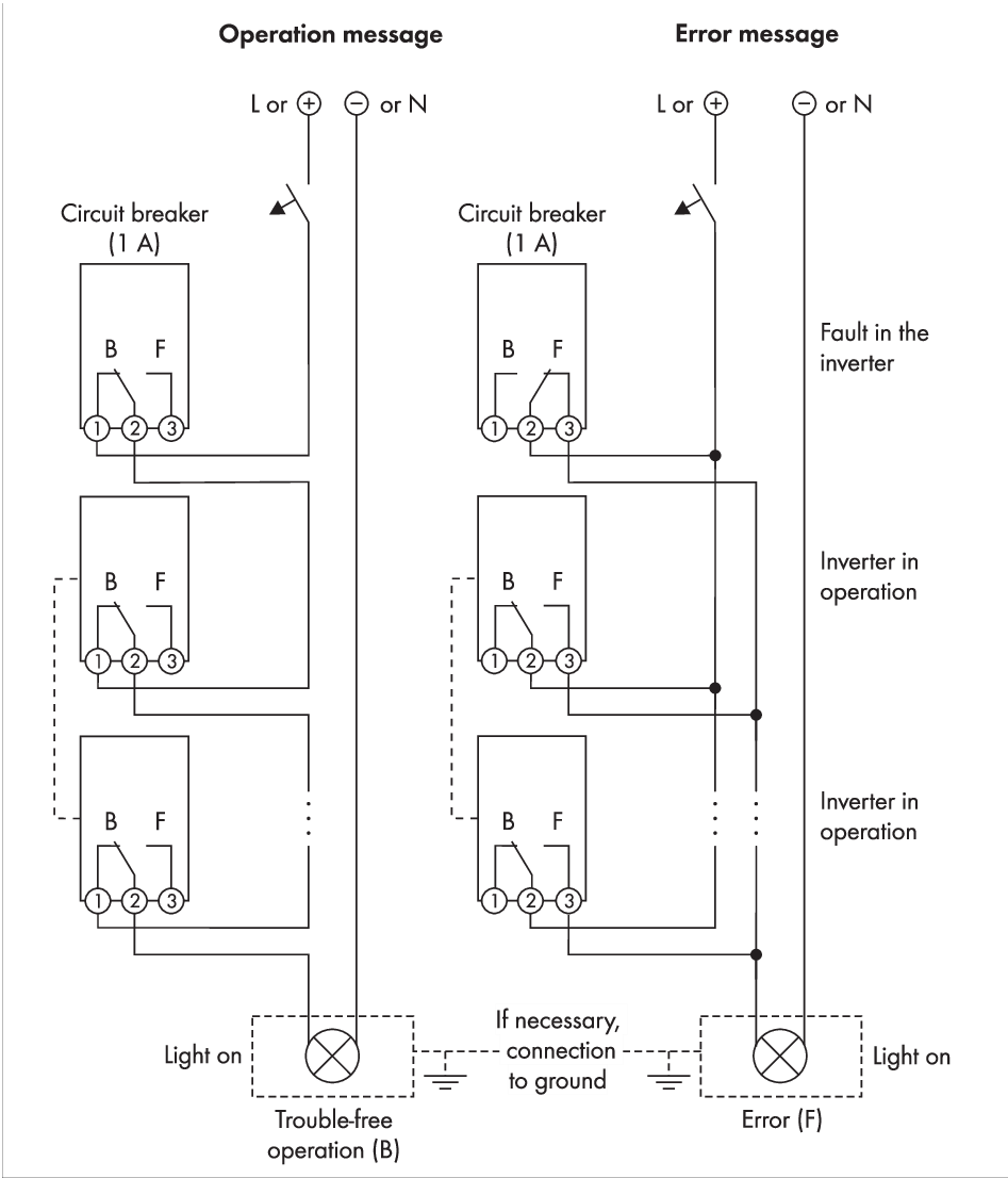
Circuit diagram with multiple inverters for connection to an operation indicator and circuit diagram for connection to a fault indicator (example)
Controlling loads via the multifunction relay or charging batteries depending on the power production of the PV system
The multifunction relay can control loads or charge batteries power-dependently. To enable this function, you must connect a contactor (K1) to the multifunction relay. The contactor (K1) switches the operating current for the load on or off. If you want batteries to be charged depending on the available power, the contactor activates or deactivates the charging of the batteries.
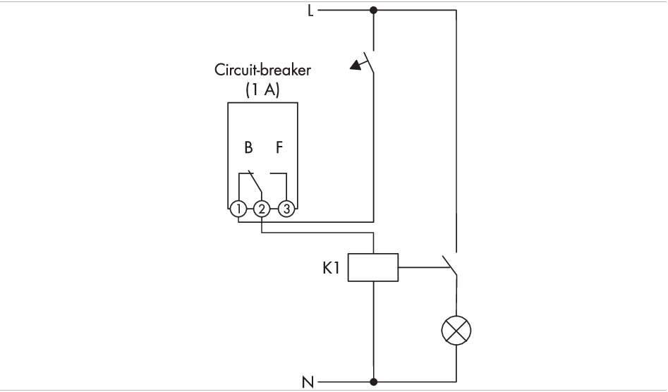
Wiring diagram for connection for controlling a load or for the power-dependent charging of the batteries
Reporting the switching status of the grid relay
The multifunction relay can trip a signal to the grid operator as soon as the inverter connects to the utility grid. To enable this function, the multifunction relays of all inverters must be connected in parallel.
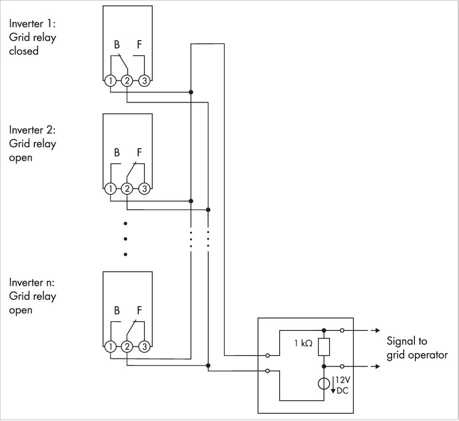
Wiring diagram for signaling the switching status of the grid relay (example)