Connecting the PV Array
 Qualified person
NOTICE
Destruction of the inverter due to overvoltage
If the open-circuit voltage of the PV modules exceeds the maximum input voltage of the inverter, the inverter can be destroyed due to overvoltage.
- If the open-circuit voltage of the PV modules exceeds the maximum input voltage of the inverter, do not connect any strings to the inverter and check the design of the PV system.
NOTICE
Destruction of the measuring device due to overvoltage
- Only use measuring devices with a DC input voltage range of 1000 V or higher.
Procedure:
- Ensure that the circuit breaker is switched off from all three line conductors and that it cannot be reconnected.
- If the ESS is plugged in, remove the ESS.
- If the protective cover is mounted, loosen the two screws of the protective cover using an Allen key (AF 5) and remove the protective cover.
- Ensure that there is no ground fault in the PV array (see service manual at www.SMA-Solar.com).
- Check whether the DC connectors have the correct polarity.
- Ensure that the open-circuit voltage of the PV array does not exceed the maximum input voltage.
- Connect the assembled DC connectors to the inverter.
- The DC connectors snap into place.
- Do not insert the sealing plugs directly into the DC inputs on the inverter.
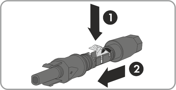
- For unused DC connectors, push down the clamping bracket and push the swivel nut up to the thread.
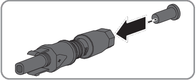
- Insert the sealing plug into the DC connector.
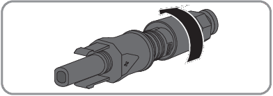
- Tighten the DC connector (torque: 2 Nm).
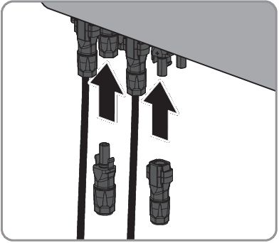
- Insert the DC connectors with sealing plugs into the corresponding DC inputs on the inverter.
- The DC connectors snap into place.
- Ensure that all DC connectors are securely in place.
If the DC connector is equipped with a DC cable of the wrong polarity, the DC connector must be assembled again. The DC cable must always have the same polarity as the DC connector.
NOTICE
Damage to the inverter due to moisture ingress
The inverter is only properly sealed when all unused DC inputs are closed with DC connectors and sealing plugs.