
View from Below
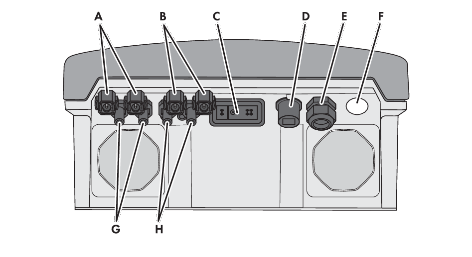
Connection areas and enclosure openings at the bottom of the inverter
|
Position |
Designation |
|---|---|
|
A |
Positive DC connectors, input A |
|
B |
Positive DC connectors, input B |
|
C |
Pin connector for the ESS |
|
D |
Pin connector with filler plug for the network connection |
|
E |
Cable gland M25 with filler plug for the data cables |
|
F |
Enclosure opening for the AC cable |
|
G |
Negative DC connectors, input A |
|
H |
Negative DC connectors, input B |