
Assembling the AC Field Plug
You can use the AC field plugs included in the delivery for different purposes:
-
Connecting the AC cable of the first inverter to the Sunny Multigate. However, this connection can also be made using a junction box.
-
Using two AC field plugs to bridge greater distances between two inverters. The AC cables available at SMA for connecting the inverters have a limited length ( > Spare Parts and Accessories).
Overview

Elements of the AC field plug
|
Position |
Designation |
|---|---|
|
A |
Insulator |
|
B |
Enclosure |
|
C |
Seal |
|
D |
Screw connection |
Additionally required material (not included in the scope of delivery):
- 3 bootlace ferrules 2.5 mm² (14 AWG)
- Cable complying with UL6703 (PV wire)
- Cable shears with insulated handles, 165 mm (6.5 in)
- Stripping knife with straight blade, TiN 8 mm to 28 mm (0.3 in to 1.1 in)
- Insulation stripping tool, 10 mm² (7 AWG)
- Crimping tool for bootlace ferrules up to 10 mm² (7 AWG)
- Torque screwdriver, 1.4" hexagon socket, 0.3 Nm to 1.2 Nm (2.7 in-lb to 10.6 in-lb)
- Cross-head screwdriver bit, 1.4" hexagon, length: 25 mm (1 in)
- Torque wrench, scale adjustable from 2 Nm to 20 Nm (17.7 in-lb to 177 in-lb)
- Crow-Ring wrench, AF 25
- Square insertion tool, outer square: 3/8 in, inner square: 9 mm x 12 mm
- Screwdriver, insulated with blade width 4 mm (0.16 in) and blade thickness 0.8 mm (0.03 in)
 DANGER
Danger to life due to electric shock
- Do not disconnect or connect the AC field plug under load.
- Only assemble the AC field plug in a dry environment.
- Observe the operating temperature range of −40°C to +85°C (−40°F to +185°F).
- Note and adhere to the requirements of the National Electrical Code®, ANSI/NFPA 70).
Cable requirements:
- Cable type: UL listed as per UL6703 (PV wire, QPOR) Power and Control Tray cable, type TC-ER (LAPP-Tray Cable II A 3 G AWG 14/46 BK). With this cable type, the use of a conduit is not required.
- Cable type: copper wire
- Cable cross-section: 2.5 mm² (14 AWG)
- External diameter of the cable sheath: 8.8 mm to 9.6 mm (0.35 in to 0.38 in)
- Wire cross-section: 30 AWG
- Number of stranded wires: 46
- Temperature: at least +90°C (+194°F) wet/dry
- This cable must be installed in an inaccessible location or in a National Electrical Code® compliant conduit.

Removing and reassembling the AC field plug is only possible within 72 hours
- In total, the AC field plug may at maximum be removed three times and only within the first 72 hours after the first assembly.
- After the period of 72 hours has expired, the AC field plug must not be removed.
- The cable must be shortened again before each assembly.
- Only disconnect and disassemble the AC field plug following the instructions in this document ( > Disconnecting the AC Field Plug).
Procedure:
To assemble and connect the AC field plug, carry out the following steps in the given sequence. The exact procedure is described in the paragraphs below.
-
Assembling the Cable
-
Premounting the AC Field Plug
-
Mounting the Insulator
-
Completing Mounting of the AC Field Plug
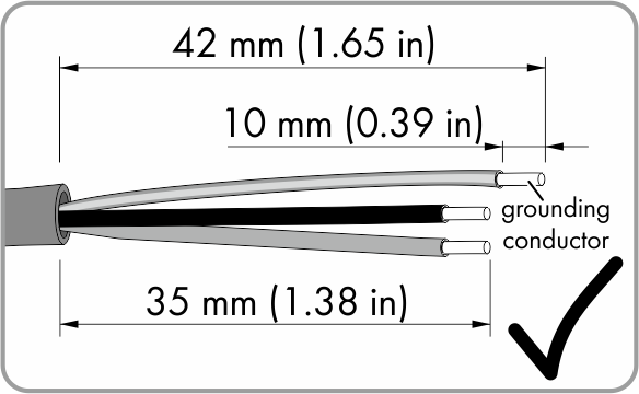
Assembling the Cable
- Shorten the cable to the desired length using cable shears.
- Dismantle the shortened cable by 42 mm (1.65 in) using the stripping knife. Take care not to damage the individual insulated conductors.
- Shorten L1 and L2 by 7 mm (0.28 in).
- Using the insulation stripping tool, strip the insulation of the three individual conductors by 10 mm (0.39 in) each (tolerance: ± 1 mm/± 0.04 in). Take care not to damage the individual stranded wires.
- The cable is assembled.
- Push one bootlace ferrule onto each stripped insulated conductor up to the stop. Do not touch the stranded wires with your fingers and do not change the twist direction of the stranded wires.
- Crimp the bootlace ferrule tightly using a crimping tool.
- Ensure that a crimping length of max. 2.4 mm (0.09 in) is maintained.
Premounting the AC Field Plug
- Slide the screw connection over the cable with the bootlace ferrules. Ensure that the thread of the screw connection is facing the bootlace ferrule.
- Use your fingers to push the seal as far as possible into the plug enclosure.
- Lead the plug enclosure with the seal over the cable. The thread must be facing the thread of the screw connection.
Mounting the Insulator
- Push the stranded wires with the bootlace ferrules up to the stop in the premounted pin connectors inside the insulator. L1 must be plugged into pin connector L1, L2 into pin connector L2 and the grounding conductor into the pin connector with the symbol
 .
. - The bootlace ferrules are no longer visible.
- Tighten the three screws in the insulator using a screwdriver (torque: 0.8 Nm (7 in-lb)).
- Make sure that the individual conductors are positioned securely in the correct pin connectors of the insulator.
Completing Mounting of the AC Field Plug
- Push the AC plug enclosure onto the insulator.
- Both parts snap together. The catch mechanism on the insulator and on the AC plug enclosure must be correctly aligned.
- Screw the nut of the AC plug enclosure on and use a torque wrench to tighten the nut twice in a row with two different torques.
-
First tighten the nut with a torque of 3.3 Nm (29.2 in-lb.). Set the value 3.0 Nm (26.6 in-lb) at the scale of the torque wrench specified by SMA.
-
Then tighten the nut with a torque of 5.1 Nm (45.1 in-lb). Set the value 4.6 Nm (40.7 in-lb) at the scale of the torque wrench specified by SMA.
-
Hint: The given torque setting only applies to the torque wrench specified by SMA. The value to be set on the torque wrench is lower than the actual value (for more information on the calculation of the torque to be set, go to www.stahlwille.com). A torque wrench consists of the following components: torque wrench (basic device), square insertion tool and crow's foot wrench.
- Make sure that the nut of the AC plug enclosure is securely fastened.