Connecting Additional Grounding
If grounding of the inverter via the equipment grounding conductor is required, grounding must be carried out via the inverter enclosure. A grounding set is included with every inverter. You can ground each inverter separately or connect several inverters to one grounding conductor. The grounding conductor of the utility grid must be connected to the grounding conductor terminal of the Sunny Multigate.
 WARNING
Danger to life due to electric shock in case of installations without equipment grounding conductor
In case of installations without equipment grounding conductor, grounding of the inverters is ensured via the AC cable only. There is a risk of electric shock under fault conditions at the inverter if PV modules are connected to the inverter and the connection to the grounding conductor via the Sunny Multigate-US is interrupted.
- Observe the installation sequence ( > Electrical Connection).
- Before disconnecting a single inverter on the AC side: Disconnect all following inverters of the PV system on the DC side.

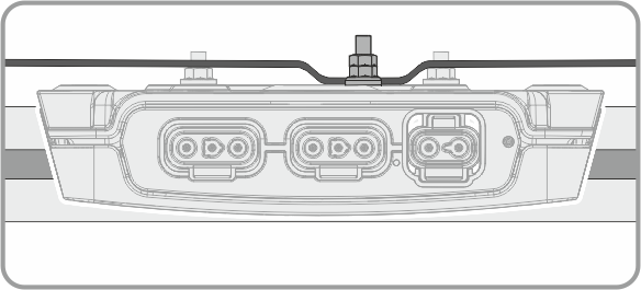
Information on the figures in this section
The figures show an example of the mounted inverter with the lid facing towards the roof. The procedure for grounding a mounted inverter with the rear side facing towards the roof or the wall is identical and is therefore not shown as a figure in this section.
Overview

Material for equipment grounding included in the scope of delivery
|
Position |
Designation |
|---|---|
|
A |
Grounding bolt |
|
B |
Clamping bracket |
|
C |
Washers |
|
D |
Hexagon nuts |
Ground the inverter enclosure as follows:
Cable requirements:
- Only use copper cables.
- Use only cables made of solid wire.
- Cross-section of the equipment grounding conductor: 4 mm² to 16 mm² (12 AWG to 6 AWG)
NOTICE
Damage to the PV module due to insufficient clearance between the inverter and the PV module bottom side
For roof mounting, the clearance from the inverter to the bottom side of the PV module must be at least 30 mm (1.2 in). This will prevent the grounding bolt from damaging the PV module.
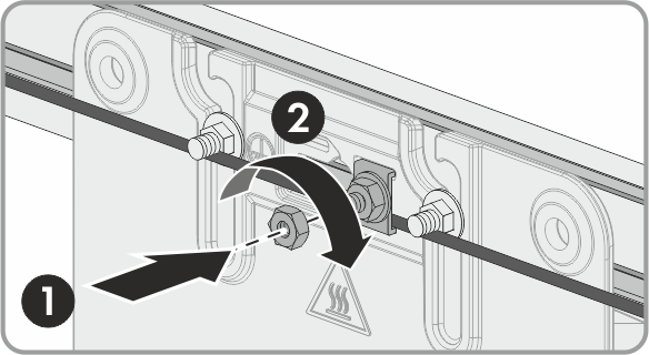
Procedure:
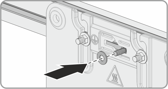
- Insert the grounding bolt into the hole with the bolt head facing the support surface (e.g. rail) and push it to the right-hand stop.
- Position a washer on the grounding bolt.
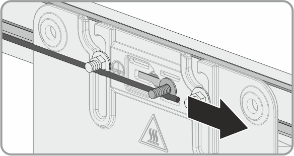
- Align the equipment grounding conductor horizontally underneath or on top of the grounding bolt.
- Position the clamping bracket on the grounding bolt over the equipment grounding conductor. Depending on the conductor cross-section, the clamping bracket will not necessarily lock into place in the horizontal slots.
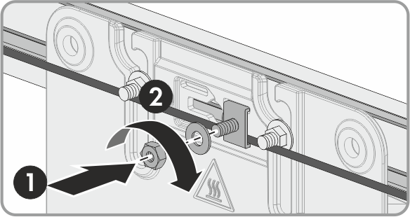
- Place the second washer and one hexagon nut on the grounding bolt and tighten (torque: 3.5 Nm (31 in-lb)).
- Place the second hexagon nut on the grounding bolt and tighten (torque: 3.5 Nm (31 in-lb)).
- Bend the equipment grounding conductor to ensure that there is no contact with the inverter enclosure.
- Connect the equipment grounding conductor to the equipotential bonding of the AC distribution board.


NOTICE
Prevention of contact corrosion by bending the equipment grounding conductor
The equipment grounding conductor should not be in contact with the inverter enclosure. Contact may result in corrosion at the contact surface. Contact between fastening screws and nuts is permitted.