
Requirements for Mounting the Inverter
Requirements for the mounting location:
 WARNING
Danger to life due to fire or explosion
Despite careful construction, electrical devices can cause fires.
- Do not mount the inverter in areas containing highly flammable materials or gases.
- Do not mount the inverter in a potentially explosive atmosphere.
WARNING
Risk of burns due to hot surfaces
The surface of the inverter can get very hot. Touching the surface can result in burns.
- Mount the inverter in such a way that it cannot be touched inadvertently.
- Do not touch hot surfaces.
- Wait ten minutes for the surface to cool sufficiently before performing any work on the inverter.
- Observe the warning messages on the inverter.
- To ensure optimum operation, the ambient temperature should be between -40°C and 65°C.
- The mounting location should not be exposed to direct solar irradiation. Direct solar irradiation can cause the inverter to overheat. As a result, the inverter reduces its power output.
- Climatic conditions must be met ( > Technical Data).
- The mounting location must be inaccessible to children.
- The mounting location must be suitable for the weight and dimensions of the inverter ( > Technical Data).
- The inverter must be mounted on the roof on the framework underneath the PV modules or on a solid support surface (e.g. concrete, brickwork). In living areas, ensure that the support surface is not drywall or similar. When in operation, the inverter makes noises which can be perceived as a nuisance.
- When mounting on the framework, the mounting position should preferably be in the center of the PV module. This will ensure a longer electrical endurance of the inverter.
Dimensions for mounting:

Position of the anchoring points
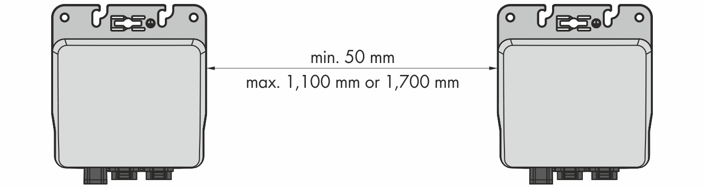
Recommended clearances:
- When using an AC cable of 1.40 m: min. 50 mm to max. 1.10 m
- When using an AC cable of 2.0 m: min. 50 mm to max. 1.70 m
- Greater distances between two inverters can be bridged using an additional cable and two AC field plugs ( > Assembling the AC Field Plug).
- Observe recommended clearances to the inverters or other objects.
Recommended clearances
Minimum Clearance between Inverter and PV Module Bottom Side:
NOTICE
Damage to the PV module due to insufficient clearance between the inverter and the PV module bottom side
For roof mounting, the clearance from the inverter to the bottom side of the PV module must be at least 30 mm. This will prevent the grounding bolt from damaging the PV module.

Minimum clearance of the inverter to the bottom side of the PV module
Permitted Mounting Position:
 DANGER
Electric shock due to ingress of moisture
- During mounting, make sure that the connection area of the inverter remains dry.
As soon as the connector and protective cap are plugged in, the connection area will be protected from moisture ingress. Thus, the inverter complies with degree of protection IP65.
- In order to ensure optimum operation and long electrical endurance of the inverter, install each inverter centered under the respective connection socket of the PV module.
- For installations that are integrated into the building, do not install the inverter directly on the back side of the PV module. This will prevent the inverter power from being reduced due to excessive ambient temperature.