Connecting the Inverter to the Utility Grid
 Qualified person
Requirements:
The connection requirements of the grid operator must be met.
The grid voltage must be within the permissible range. The exact operating range of the inverter is specified in the operating parameters.
Procedure:
- Disconnect the AC miniature circuit breaker and secure against reconnection.
- Remove the adhesive tape from the enclosure opening for the AC connection.
- Insert the cable gland into the opening and tighten it with the counter nut from the inside.
- Guide each cable into the inverter. In the process, lay each cable in such a way that they do not come into contact with the communication assembly.
- Connect the grounding conductor to the grounding terminal:
-
Strip off the conductor insulation by 18 mm.
Insert the screw through the conical spring washer, the clamping bracket and the washer.
-
Guide the conductor between the washer and clamping bracket and tighten the screw (TX 25) (torque: 6 Nm ± 0.3 Nm).
- Plug the terminal block for the AC connection in the AC-out slot in the inverter, and tighten it with a flat-blade screwdriver (blade width: 3.5 mm) (torque: 0.3 Nm).
- Ensure that the terminal block is securely in place and the screws are tightened.
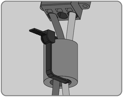
- Thread the conductors L and N through the ferrite.
- Strip off the conductor insulation of L1 and N 18 mm.
- In the case of fine stranded wire, provide the conductors with a bootlace ferrule.
- First insert the conductor into the terminal point all the way to the lock (round opening). Then insert a flat-blade screwdriver (blade width: 3.5 mm) as far as it can go into the actuation shaft (rectangular opening). Hereby the lock opens and the conductor can be placed into the terminal point as far as possible. After the connection has been made, the flat-blade screwdriver must be pulled out of the actuation shaft.
- Connect the conductors to the terminal block for the AC connection:
-
Connect the neutral conductor to the terminal block in accordance with the labeling. Insert the conductor into the corresponding terminal point (round opening) up to the stop.
-
Connect L to the terminal block in accordance with the labeling. Insert the conductor into the corresponding terminal point (round opening) up to the stop.
- Ensure the conductors are plugged into the terminal points (round openings) as far as is will go and not into the actuation shafts (rectangular openings).
- Ensure that the terminal points are allocated to the correct conductors.
- Ensure that the conductors are plugged completely into the terminal points up to their insulation.
- Position the ferrite as close as possible to the bottom of the AC connection terminal block and secure using the cable tie.


Connection of conductors of finely stranded wire
To connect conductors made of finely stranded wire, each terminal point must be opened.
WARNING
Fire hazard due to faulty conductor connection
If the conductors are inserted into the actuation shafts (right-angled openings), a fire may occur during inverter commissioning.