Mounting the product
Additionally required mounting material (not included in the scope of delivery):
2 screws suitable for the support surface (diameter: 8 mm)
2 washers suitable for the screws
Where necessary, 2 screw anchors suitable for the support surface and the screws
 CAUTION
Risk of injury due to weight of product
Injuries may result if the product is lifted incorrectly or dropped while being transported or mounted.
- Transport and lift the product carefully. Take the weight of the product into account.
- Wear suitable personal protective equipment for all work on the product.
Procedure:
- Opening the Connection Unit Unscrew all 6 screws (TX25) and carefully remove the enclosure lid toward the front.
- Unscrew the 2 screws on the right and left side of the Power Unit (TX25). As a result, the Power Unit and the Connection Unit are not connected to one another.
- Disconnect the Connection Unit from the Power Unit.
- Align the connection unit horizontally and vertically. Mark the position of the drill holes using the brackets.
- Drill the holes in the marked positions.
- Insert screw anchors into the drill holes if the support surface requires them.
- Secure the Conection Unit horizontally using screws and washers.
- Check whether the Connection Unit is firmly positioned.
- Plug the Power Unit into the Connection Unit. Make sure that the screw holes on the left and right sides of the Power Unit are directly over those of the Connection Unit; and the cables protruding from the Power Unit must not be pinched.
- Tighten 2 screws on the right and left side of the Power Unit (TX25) (torque: 6 Nm ± 0.3 Nm).
- Remove the adhesive tape with which the ribbon cable is attached to the Connection Unit.
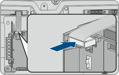
- Pull the ribbon cable used to connect the communication assembly to the Power Unit into the Connection Unit, and plug it into the jack on the communication assembly.
- Insert the ribbon cable used to connect the communication assembly to the battery interface module into the jack on the battery interface module and lock it.
- Insert the DC terminal block into the DC-in slot. Tighten the screws using a flat-blade screwdriver (blade width: 3.5 mm (0.14 in)) (torque: 0.3 Nm (2.65 in-lb)).