
Connect the utility grid along with power and signal cables for backup operation
 Qualified person
If there are multiple inverters in the system but backup loads are only connected to one of them, the backup loads should be connected to the inverter that is configured as the System Manager.
Requirements:
The AC cables for connecting to the utility grid, power and signal cables for backup operation must be pre-assembled ( > Cable Requirements).
Additionally required material (not included in the scope of delivery):
For SMA Backup Secure (secure power supply operation): 1 standard commercial socket
For SMA Backup Secure (secure power supply operation): 1 standard commercial switch
1 conduit (trade size: 19.05 mm (0.75 in) or smaller with suitable reducer bush)
Sealing compound for sealing the join between the conduit and inverter if a weep hole has been added to the conduit
1 rain-tight conduit fitting or conduit fitting for wet locations complying with UL 514B (trade size: 19.05 mm (0.75 in) or smaller with suitable reducing bush)
Procedure:
- Disconnect the inverter from all voltage sources ( > Disconnecting the Inverter from Voltage Sources).
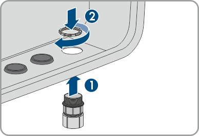
- Remove the filler plug from the first enclosure opening from the right.
- Insert the conduit fitting in the first enclosure opening from the right and tighten with the counter nut from the inside.
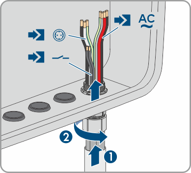
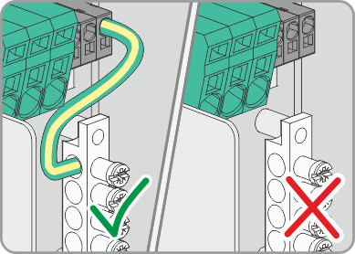
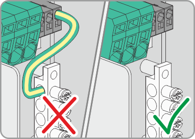
- Run the AC conductors including the signal cable and power cable for backup operation through the cable conduit into the inverter and fasten the cable conduit to the conduit fitting.
- Run L1, L2 and N for the AC connection through the ferrite.
- Secure the ferrite with a cable tie.
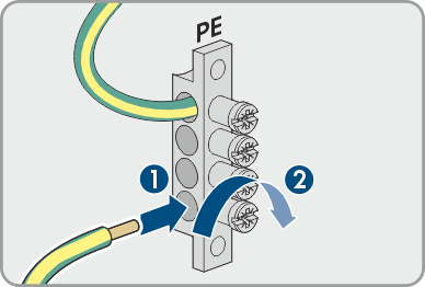
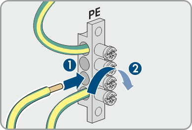
- Connect the grounding conductor for the AC connection to the busbar according to the label, as short as possible without the conductor being under tension. To do so, insert the conductor into the busbar against the stop and tighten the screw (PZ2, minimum torque 2.5 Nm).
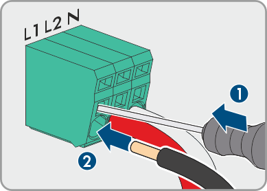
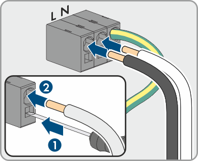
- Attach L1, L2, and N of the AC connection to the AC terminals according to the labels. To do so, stick a flathead screwdriver (4 mm (0.16 in)) into the top opening of the terminal and insert the cable into the lower opening against the stop. Then remove the screwdriver.
- Connect the conductors N and L of the power cable for the backup operation to the SPS connection terminals according to the labels.
- Connect the grounding conductor for the AC connection to the busbar according to the label, as short as possible without the conductor being under tension. To do so, insert the conductor into the busbar against the stop and tighten the screw (PZ2, minimum torque 2.5 Nm).
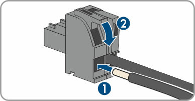
- Attach the conductors for the secure power supply operation switch to the 2-pole connector.
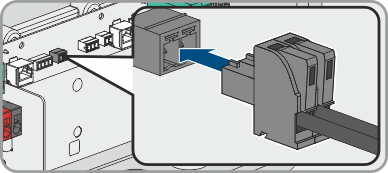
- Plug the connector into the SPS slot. The connector must snap audibly into place.
- With SMA Backup Secure: Ensure that the cable bridge for grounding the N conductor is installed.
- With SMA Backup Select: Ensure that the cable bridge for conductor N is not installed.
- Tug lightly to ensure that all conductors are secured in the terminals.
- With SMA Backup Secure: Connect the conductors to socket and switch.
- With SMA Backup Select: Connect the conductors to SMA Backup Select (see manual for SMA Backup Select).
- If a weep hole has been added to the conduit, seal the conduit with sealing compound.

Also see: