
Interior View
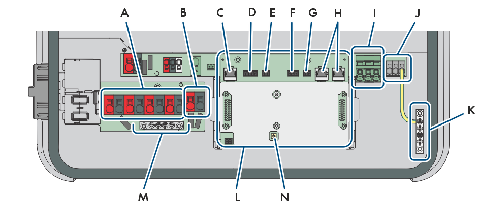
Connection Area of the Inverter
Position | Designation |
|---|---|
A | PVA, PVB, PVC and, depending on the power class,PVD terminals for connecting the PV modules |
B | Connection terminals BAT+ and BAT - for battery power cables |
C | Network connector BATTERY for connecting the battery communication |
D | Slot E-METER for connecting an energy meter per RS485 |
E | Slot SPS for the signal cable of the backup operation |
F | MFR slot for connection to the multifunction relay |
G | Terminal block GSI for fast-stop switch connection |
H | Network ports LAN-1 and LAN-2, e.g., for connecting energy meter, router, battery communication system, communication system for other PV inverters, or other Ethernet-capable devices |
I | Connection terminals AC for AC cables |
J | SPS terminals for the power cable of the backup operation |
K | Busbar for grounding the AC connection |
L | Communication assembly |
M | Busbar for grounding the DC connection |
N | Wi-Fi antenna socket |