
Dynamic load management
Dynamic load management provides the option to adjust the charging current of several charge point optimally to the available current. Dynamic load management is designed to be local load management. The charging points are connected to each other via a network connection and are configured according to the requirements via the user interface.
Additional devices like gateways, controllers or interface adapters are not necessary. Therefore, load management is easy to extend. Additional charge points can be added and integrated into the network simply.
Local load control can also be integrated into an existing or planned energy management system via standard interfaces like EEBus, Modbus TCP/IP and OCPP. This makes overload charging at a PV system or integration into building/control technology easy to implement.
Local load management can alternatively be supplemented by local load measurement. This is often desirable if the new charging infrastructure to be procured is connected to the existing building connection of a property, for example, and the building junction box will be shared. The possible power reserves of the power connection for the charging infrastructure are usually unknown. Or the power connection needs to be optimally used and not cause additional costs (peak shaving).
To accomplish this, an (additional) energy meter at the building junction box is simply integrated into the charge point network via Modbus TCP and taken into account when the current is calculated.
Technical requirements
The building junction box, supply line or branch of a sub-distribution can be limiting factors of the charging current at charge points. This limitation initially represents the upper limit of the total current to be distributed. Therefore, in a sub-distribution at a charge point that has 32 A (22 kW) available, for example, only the following installations without dynamic load management can be implemented:
Example without load management:
Without load management, the charge point would always make the maximum charging current available. In other words, each electric vehicle would be guaranteed to be charged with the maximum current over the entire time of the charging process. But not many vehicles do this. A current of 32 A is not used for the entire charging time or parking time during which the vehicle is connected, either. But the maximum current of 32 A is permanently reserved for the charge point when the vehicle is connected to the charge point.
Due to the continuous reservation of the charging current, theoretically only a 22 kW charge point can be connected to the sub-distribution without exceeding the connected load. If the need for charging infrastructure increased, the sub-distribution would have to be extended or renewed.
Example with load management:
With the help of load management, the problems described above can be solved. The load control can distribute the reserves of unused charging points to other charging points and enable the installation of charging points whose theoretical total power exceeds the actual available power of the electricity supply.
The currents are monitored with phase accuracy. The system takes into account whether the vehicle is charging on a single line conductor or line conductors. The phase rotation of the charge points to each other is also considered. This leads to the optimal distribution of the available currents.
Load management operating modes
The load management system has various operating modes and options for optimizing the load on the basis of availability and consumption. Depending on how a system is structured, alongside the charging points there are sometimes loads that cannot be controlled (e.g., loads in a property or building/commercial establishment) and of course have an influence on the total amount of available current.
For this reason, the most common configurations are:
Load management without additional loads (and therefore without external measurement)
Load management with additional, partially unknown loads and external measurement
Both cases are there to distribute charging current optimally and to avoid overstepping a definable load limit in order to prevent overload.
Connection example of load management without external power measurement

Connection example of 3 charging stations without external power measurement
Connection example of load management with external power measurement
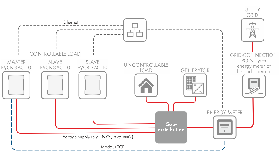
Connection example of 3 charging stations with external power measurement
Available charging options
Charging mode | Function |
|---|---|
DLM standard | All subordinate charging points are charged with the maximum available electric current. |
Surplus PV energy 1) | The vehicle is charged when there is enough excess power to charge with the specified minimum current. Vehicles then charge largely without energy from the grid. |
Surplus PV energy + Grid-supplied power 1) | If there is little PV energy available, a fixed amount of electricity is drawn from the grid. The vehicle can then be charged mainly with self-generated energy. |
1) *SMA EV Charger Business from firmware version 5.33.3.R.
Time-based charging
If you activate time-based charging, dynamic load management will not exceed the limit value configured in the schedules. Each entry specifies the maximum permitted current for each phase from the time entered. Each entry is valid until it is replaced by another suitable entry.
Additional information is available in the operating manual "SMA EV Charger Business" at www.SMA-Solar.com.