
Allowable Impedance Levels
Allowable Impedance Levels
Impedance (especially resistances of conductors and transformers) between the PV system and the grid cause an increase in voltage measured at the inverter terminals. In order to avoid over-voltage tripping of the inverters and excessive energy losses, AC conductors should be sized to limit the voltage drop between the inverters and the point of common coupling (PCC) to a maximum of 1% of nominal voltage.
In addition, the stability of the inverter control system is affected by the level of impedance (especially inductances of transformers) between the inverters and the point of common coupling (PCC) with the grid.
The maximum allowable impedance level for each inverter model is given in the table below.
Inverter type | Maximum allowable impedance (Zmax) |
|---|---|
STP 12-50 / STP 15-50 / STP 20-50 / STP 25-50 | 33% |
STP 125-70 | 40% |
SHP 100-21 | 50% |

PV system connected to the grid via multiple transformers
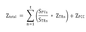
The total system impedance for a given inverter in a PV system can be calculated using the equation below:
Legend | Description |
|---|---|
ZPCC | ZPCC is the short-circuit impedance based on the short-circuit power available at the PCC
|
n | n is one of one or more transformers connected in series between the inverter and the PCC. |
SPVn | SPVn is the total nominal output power (kVA) of all inverters connected to transformer n. |
STRn | STRn is the rated power (kVA) of transformer n. |
ZTRn | ZTRn is the short-circuit impedance of transformer n. |
Conductor impedance is assumed to be 2% and has been deducted from inverter maximum allowable impedance levels.