
Disconnecting the Inverter from Voltage Sources
 Qualified person
Prior to performing any work on the inverter, always disconnect it from all voltage sources as described in this section. Always adhere to the prescribed sequence.
WARNING
Danger to life due to electric shock from destruction of the measuring device due to overvoltage
Overvoltage can damage a measuring device and result in voltage being present in the enclosure of the measuring device. Touching the live enclosure of the measuring device results in death or lethal injuries due to electric shock.
- Only use measuring devices with a DC input voltage range of 1000 V or higher.
Procedure:
- Disconnect the circuit breaker from all three line conductors and secure against reconnection.
- If the multifunction relay is used, switch off any supply voltage to the load.
- Turn the DC load-break switch to the position O.
- Wait until the LEDs have gone out and, if necessary, the load connected to the multifunction relay has been switched off.
- Use a current clamp to ensure that no current is present in the DC cables.
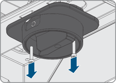
- Unscrew the two screws on the DC load-break switch using an Allen key (AF 3).
- Pull the DC load-break switch down and out of the recess.
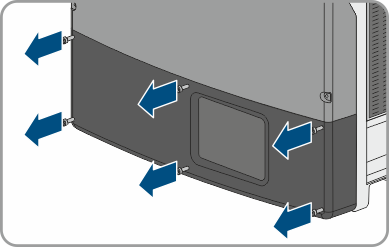
- Remove all six screws from the lower enclosure lid using an Allen key (AF 3).
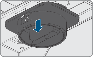
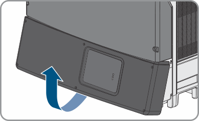
- Lift and remove the lower enclosure lid from below.
- Do not touch the DC protective cover.
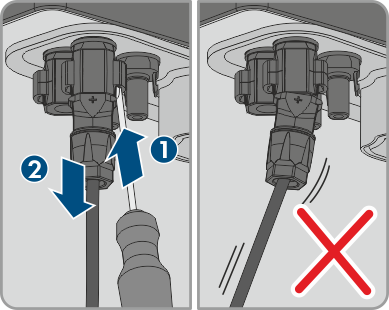
- Release and remove all DC connectors. Insert a slotted screwdriver or an angled screwdriver (blade width 3.5 mm) into one of the slide slots and pull the DC connectors out downwards. Do not pull on the cable.
- Ensure that no voltage is present at the DC inputs of the inverter.
- If the neutral conductor is connected, use an appropriate multimeter to ensure that no voltage is present at the AC connecting terminal block between L1 and N, L2 and N, and L3 and N. Insert the test probe of the multimeter into the round opening in the terminal.
- Use an appropriate measuring device to ensure that no voltage is present at the AC connecting terminal plate between L1 and PE, L2 and PE, and L3 and PE. Insert the test probe into each round opening of the terminal.
- Ensure that no voltage is present between any terminal of the multifunction relay and PE of the AC connecting terminal plate.
- Wait 20 minutes before opening the upper enclosure lid.
- Do not open the DC protective cover.
- Ground yourself before touching any component.

CAUTION
Risk of burns when touching the DC protective cover
The DC protective cover can get hot during operation.

 DANGER
Danger to life due to high voltages in the inverter
The capacitors in the inverter take 20 minutes to discharge.
NOTICE
Damage to the inverter due to electrostatic discharge
Touching electronic components can cause damage to or destroy the inverter through electrostatic discharge.