
Connecting the battery communication to Multi I/O
For the connection of the battery communication with batteries by other manufacturers, proceed as follows.

Communication between inverter and battery
- Communication between the inverter and the battery takes place via the battery communication cable via CAN bus.
Additionally required material (not included in the scope of delivery):
1 battery communication cable for the communication between inverter and battery.
Bootlace ferrules (only for multi-core stranded wire, usable length of the ferrule at least 12 mm).
Procedure:
- Disconnect the inverter from voltage sources and secure it against being switched on again ( > Disconnecting the Inverter from Voltage Sources).
- Ensure that the battery is switched off.
- Remove the protective cover from the MULTI I/O terminal.
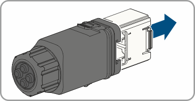
- Unscrew the union nut from the threaded sleeve of the Multi I/O connector.
- Remove the four-hole cable support sleeve from the cable gland.
- Pull the communication assembly out of the cable gland.
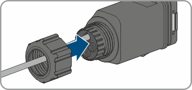
- Thread the swivel nut over the cable.
- Remove the plug from one of the enclosure openings and cut into the enclosure opening with a utility knife.
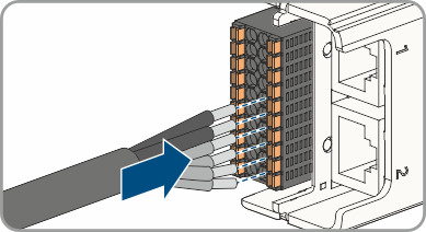
- Insert the cable into the enclosure opening.
- Strip off a maximum of 6 mm of the cable insulation.
- Connect the conductors of the connection cable to the digital inputs CAN. To do so, plug the conductors into the conductor entries and close the conductor entries. Observe the connector assignment ( > PIN assignment battery communication on Multi I/O).
- Ensure that all conductors are correctly connected.
- Ensure that the conductors sit securely in the terminal points.
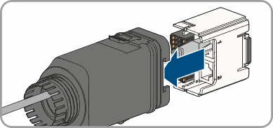
- Plug the communication assembly onto the cable gland.
- Fasten the union nut on the cable gland and screw hand-tight.
- Plug the communication assembly with the cable gland into the terminal MULTI I/O on the inverter.
- Connect the communication cable to the terminal for the battery communication. Pay attention to the assignment of the terminal and communication connection on the battery and make sure that CAN L and CAN H consist of a pair of conductors. For additional information on how to connect the battery, see Technical Information "Approved Batteries and Information on Battery Communication Connection" at www.SMA-Solar.com.
Also see: