
Connecting Signal Cables for Backup Operation
- Disconnect the inverter from voltage sources and secure it against being switched on again ( > Disconnecting the Inverter from Voltage Sources).
- Remove the protective cover from the MULTI I/O terminal.
- Unscrew the union nut from the threaded sleeve of the Multi I/O connector.
- Remove the four-hole cable support sleeve from the cable gland.
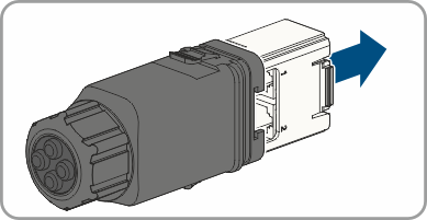
- Pull the communication assembly out of the cable gland.
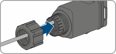
- Thread the swivel nut over the cable.
- Remove the plug from one of the enclosure openings and cut into the enclosure opening with a utility knife.
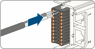
- Insert the cable into the enclosure opening.
- Strip off a maximum of 6 mm of the cable insulation.
- Connect the conductors of the connection cable to the digital inputs SPS IN. To do so, plug the conductors into the conductor entries and close the conductor entries. Observe the connector assignment.
- Ensure that all conductors are correctly connected.
- Ensure that the conductors sit securely in the terminal points.
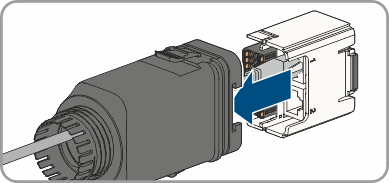
- Plug the communication assembly onto the cable gland.
- Fasten the union nut on the cable gland and screw hand-tight.
- Plug the communication assembly with the cable gland into the terminal MULTI I/O on the inverter.
Also see: