
Connecting the AC conductors
 Qualified person
Additionally required material:
1 conduit (trade size: 27 mm (1 in) or smaller with suitable reducer bush)
Sealing compound for sealing the join between the conduit and inverter if a weep hole has been added to the conduit
1 rain-tight conduit fitting or conduit fitting for wet locations complying with UL 514B (trade size: 27 mm (1 in) or smaller with suitable reducing bush)
Requirements:
The AC and DC electric circuits are isolated from the enclosure. If required by the National Electrical Code® ANSI/NFPA 70 or Canadian Electrical Code® CSA C22.1, the installer is responsible for grounding the system.
All electrical installations must be carried out in accordance with the local standards and the National Electrical Code® ANSI/NFPA 70 or the Canadian Electrical Code® CSA C22.1.
The grid voltage must be within the permissible range. The exact operating range of the inverter is specified in the operating parameters .
Procedure:
- Disconnect the miniature circuit breaker from all 3 line conductors and secure against reconnection.
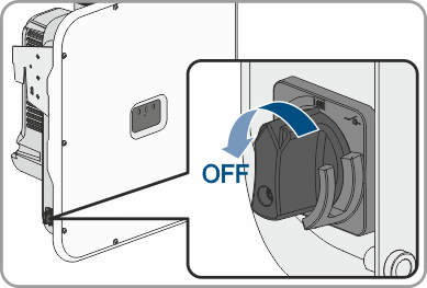
- Ensure that the DC load-break switch is in the O position / OFF.
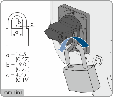
- If your country requires the DC load-break switch to be protected against reconnection, secure the DC load-break switch against reconnection with a padlock.
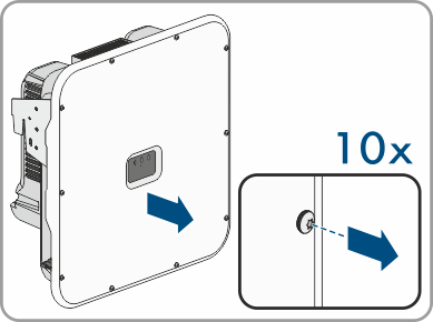
- Unscrew the screws of the enclosure lid with a Torx screwdriver (TX 25) and remove the enclosure lid carefully forward.
- Remove the adhesive tape from the enclosure opening for the AC connection.
- Attach the conduit to the enclosure opening.
- Guide the conductors from the conduit into the inverter.
- Strip off the conductor insulation by 0.71 in to 0.79 in each.
- If necessary, provide each conductor with a bootlace ferrule.
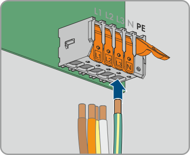
- Press the locking lever of terminal PE upward, guide the equipment grounding conductor into the terminal, and press the locking lever downward again.
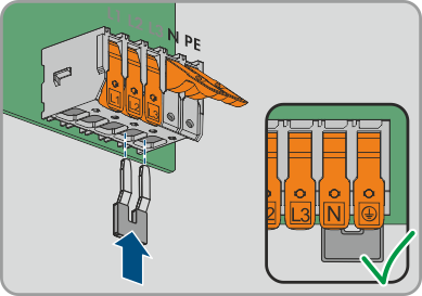
- For connection without a neutral conductor, use the jumper provided to bridge terminal blocks PE and N. For this, press the locking levers of terminals PE and N upward, guide the jumper into the terminals, and press the locking levers downward again.
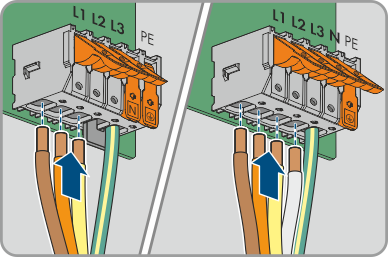
- Press the locking levers of terminals L1, L2, L3, and if applicable N upward, guide conductors L1, L2, L3, and if applicable N into the terminals according to the labeling, and press the locking levers downward again.
- Ensure that the correct conductors are assigned to all the terminals.
- Ensure that all conductors are securely in place.
- If a weep hole has been added to the conduit, seal the conduit with sealing compound.
Also see: