
Connecting the PV Array
 Qualified person
WARNING
Danger to life due to electric shock from destruction of the measuring device due to overvoltage
Overvoltage can damage a measuring device and result in voltage being present in the enclosure of the measuring device. Touching the live enclosure of the measuring device results in death or lethal injuries due to electric shock.
- Only use measuring devices with a DC input voltage range of 1000 V or higher.
NOTICE
Damage to the product due to ground fault on DC side during operation
Due to the transformerless topology of the product, the occurrence of ground faults on DC side during operation can lead to irreparable damage. Damages to the product due to a faulty or damaged DC installation are not covered by warranty. The product is equipped with a protective device that checks whether a ground fault is present during the starting sequence. The product is not protected during operation.
- Ensure that the DC installation is carried out correctly and no ground fault occurs during operation.
NOTICE
Damage to the DC connectors due to the use of contact cleaner of other cleaning agents
Some contact cleaners or other cleaning agents may contain substances that decompose the plastic of the DC connectors.
- Do not use contact cleaners or other cleaning agents for cleaning the DC connectors.
NOTICE
Destruction of the inverter due to overvoltage
If the open-circuit voltage of the PV modules exceeds the maximum input voltage of the inverter, the inverter can be destroyed due to overvoltage.
- If the open-circuit voltage of the PV modules exceeds the maximum input voltage of the inverter, do not connect any strings to the inverter and check the design of the PV system.
Requirements:
The miniature circuit breaker must be switched off and prevented from being reconnected.
The DC load-break switch must be set to OFF and, depending on local regulations, prevented from restarting using a padlock.
The cables of the PV modules must be equipped with DC connectors.
If the DC terminal cover is available as an accessory, the DC terminal cover must be mounted on the inverter and the DC cables must be routed through the conduits into the DC term cover ( > Mount the DC terminal cover (optional)).
Procedure:
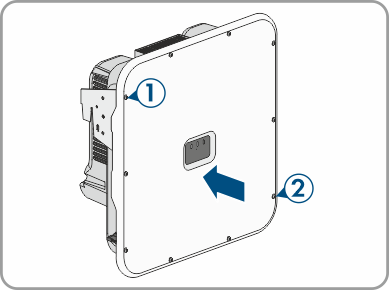
- Position the enclosure lid and first insert the upper-left (position 1) and lower-right (position 2) screws and fasten them hand-tight (TX25).
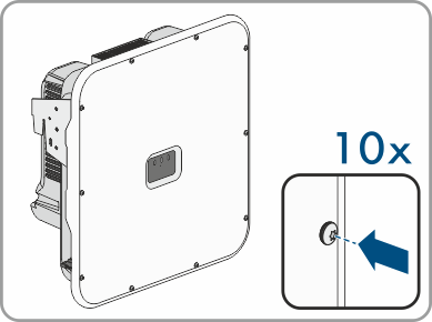
- Insert and tighten all screws (TX25, torque: 6 Nm ± 0.3 Nm (53 in-lb ± 2.65 in-lb)).
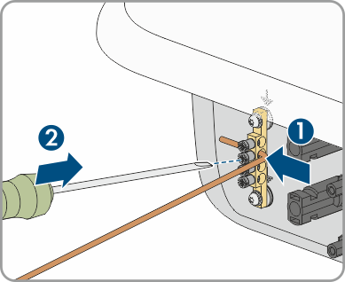
- Strip the insulation of every equipment grounding conductor by 10 mm (0.4 in).
- Connect every equipment grounding conductor of the PV modules to the equipment grounding bar. To do this, plug the equipment grounding conductor into a contact opening on the equipment grounding bar and tighten the corresponding screw using a cross-head screwdriver (torque: 4 Nm (35 in-lb).
- Measuring the voltage of the PV array. Ensure that the maximum input voltage of the inverter is adhered to and that there is no ground fault in the PV system.
- Check whether the DC connectors have the correct polarity.
- If the DC connector is equipped with a DC cable of the wrong polarity, the DC connector must be reassembled. When this is done, the DC cable must always have the same polarity as the DC connector.
- Ensure that the open-circuit voltage of the PV array does not exceed the maximum input voltage.
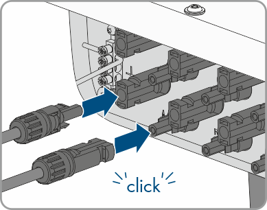
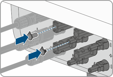
- Connect the assembled DC connectors to the inverter.
- The DC connectors snap into place.
- Ensure that all DC connectors are securely in place.
- Seal the DC connectors that are not required on the product with the supplied sealing plugs.
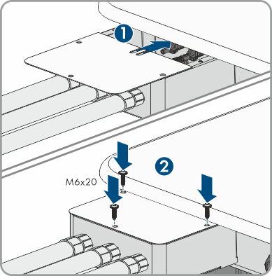
- If the DC terminal cover is available as an accessory, mount the cover of the DC terminal cover with the 3 M6x20 screws (TX25, torque: 6 Nm (53 in-lb)).
NOTICE
Damage to the product due to sand, dust and moisture ingress if the DC inputs are not closed
The product is only properly sealed when all unused DC inputs are closed with sealing plugs. Sand, dust and moisture penetration can damage the product and impair its functionality.
Also see: