
Commissioning the Inverter
 Qualified person
Requirements:
- The inverter must be correctly mounted.
- The circuit breaker must be correctly rated and mounted.
- All cables must be correctly connected.
- Unused DC inputs must be sealed using the corresponding DC connectors and sealing plugs.
- The country data set must be set correctly for the country or the purpose.
- Unused enclosure openings must be sealed tightly. The factory-mounted filler plugs can be used for that purpose.
Procedure:
- Connection to the SMA Speedwire/Webconnect data module (see installation manual of the SMA Speedwire/Webconnect data module). Use the supplied cable gland M32 for this purpose.
- Make sure that the AC cable is routed so that it cannot be damaged by the partition in the lower enclosure lid.
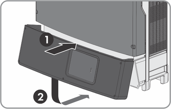
- Insert the lower enclosure lid from above and flip it down. The screws must protrude from the lower enclosure lid.
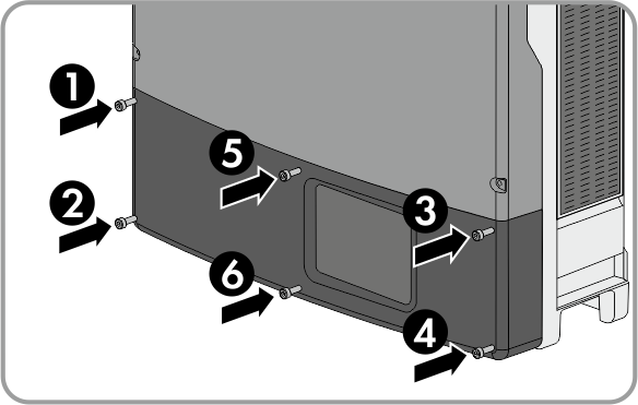
- Tighten all six screws with an Allen key (AF 3) in the order 1 to 6 (torque: 2.0 Nm ± 0.3 Nm). By tightening the screws in the prescribed order, you avoid warping the enclosure lid, which would keep it from sealing correctly. Tip: If the screws fall out of the lower enclosure lid, insert the long screw into the lower middle hole and the five short screws into the other holes.
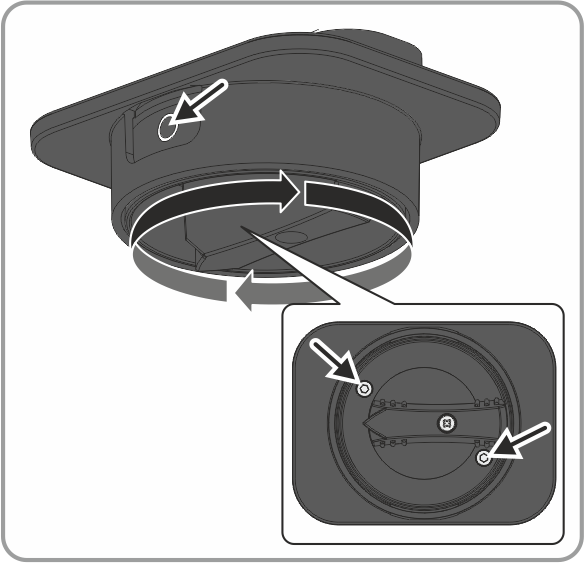
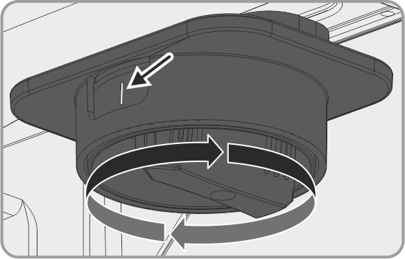
- Set the DC load-break switch to position O so that both mounting screws are visible.
- Insert the DC load-break switch firmly into the recess on the inverter. During this process, the DC load-break switch must still be in position O and aligned so that the screws are positioned over the threads.
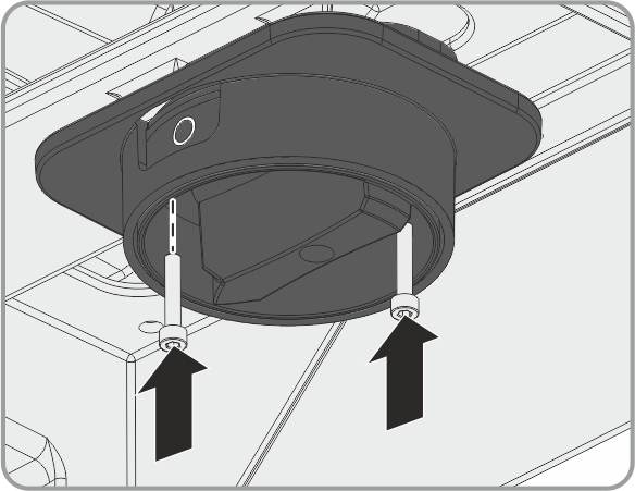
- Fasten the two screws using an Allen key (AF 3) (torque: 2 Nm ± 0.2 Nm).
- Turn the DC load-break switch to the position I.
- Switch on the circuit breaker of all three line conductors.
- All three LEDs start to glow and the start-up phase begins. The start-up phase may take several minutes.
- The green LED is glowing and the display alternates between the firmware version, the serial number of the inverter, the NetID, the configured country data set and the display language.
- Once the DC input voltage is sufficiently high and the grid-connection conditions are met, the inverter will start operation.
- Eliminate the error ( > Troubleshooting).
The green LED is flashing?
Possible cause of error: the DC input voltage is still too low or the inverter is monitoring the utility grid.
The red LED is glowing and an error message and event number appear in the display?