Connecting the Inverter to the Utility Grid
 Qualified person

Cables to be connected by means of cable glands
As standard for this inverter, the cables are to be connected by means of cable glands. SMA Solar Technology AG recommends using the cable glands included in the delivery. If required, adapters for conduits can be mounted on the enclosure openings of the inverter instead of using cable glands. Thus, cables laid in the conduits can be routed into the inverter. When using conduits, all locally applicable laws, standards and directives must be observed and the conduits as well as the enclosure openings must be protected against penetrating moisture.
Requirements:
- The connection requirements of the grid operator must be met.
- The grid voltage must be in the permissible range. The exact operating range of the inverter is specified in the operating parameters.
Procedure:
- Disconnect the circuit breaker from all three line conductors and secure against reconnection.
- If the lower enclosure lid is mounted, loosen all screws of the lower enclosure lid using an Allen key (AF 3) and lift the enclosure lid from below and remove it.
- Remove the adhesive tape from the enclosure opening for the AC cable.
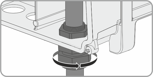
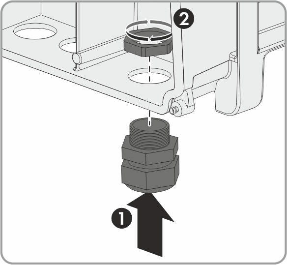
- Insert the cable gland from the outside into the enclosure opening and tighten it from the inside with the counter nut.
- Route the AC cable into the inverter through the cable gland. If necessary, slightly loosen the swivel nut of the cable gland.
- Dismantle the AC cable.
- Shorten L1, L2, L3 and, if necessary, N by 5 mm each so that PE is 5 mm longer.
- Strip all conductors by 12 mm each.
- Push the safety levers of the AC connecting terminal plate right up to the stop.
- Never connect more than one conductor per terminal.
- Press the locking levers of the connecting terminal plate for the AC cable down with your thumb only.
- Do not grip the entire connecting terminal plate for the AC cable.
- Do not place your fingers under the locking levers.
- Connect all conductors to the connecting terminal block for the AC cable in accordance with the labeling and push the locking levers down. In this case, the connection of the neutral conductor is optional and the direction of the rotating magnetic field of L1, L2 and L3 is not relevant.
- Make sure that all conductors are securely in place.
- Tighten the swivel nut of the cable gland. When using conduits, seal the enclosure opening from the inside of the adapter counter nut with putty.
CAUTION
Risk of fire if two conductors are connected to one terminal
If you connect two conductors to a terminal, a fire can occur due to a bad electrical connection.
CAUTION
Danger of crushing when locking levers snap shut
The locking levers close by snapping down fast and hard.