
Interior View
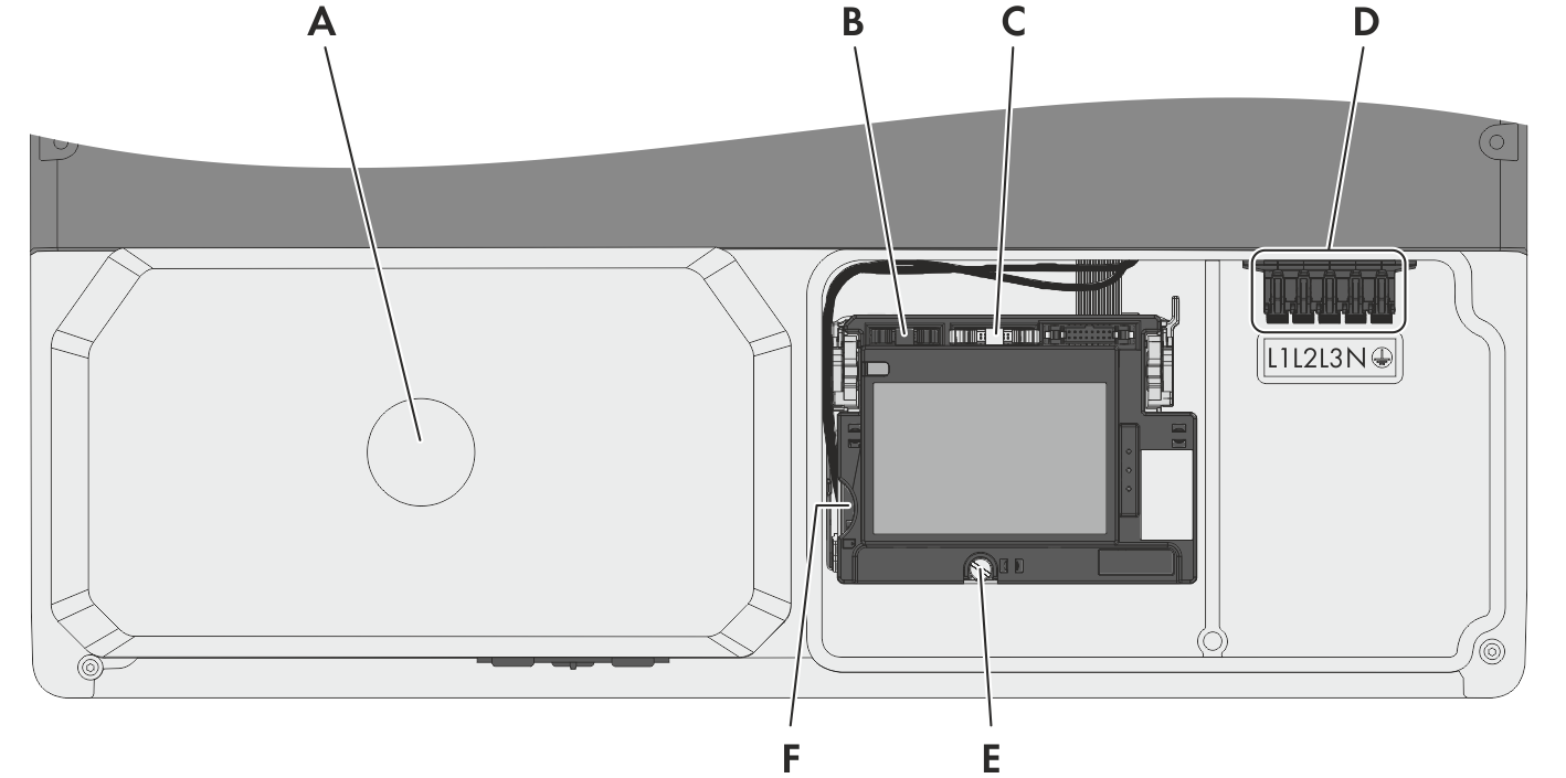
Connection areas in the interior of the inverter
|
Position |
Designation |
|---|---|
|
A |
DC protective cover |
|
B |
Pin connector for connecting the multifunction relay or the SMA Power Control Module (optional) |
|
C |
Pin connector for connecting a communication interface (optional) |
|
D |
Connecting terminal plate for connecting the AC cable |
|
E |
Screw for releasing and raising the display |
|
F |
Slot for the SD memory card (for service purposes) |