Connecting the PV Array
NOTICE
Damage to the inverter due to ground fault on DC side during operation
Due to the transformerless topology of the product, the occurance of ground faults on DC side during operation can lead to irreparable damage. Damages to the product due to a faulty or damaged DC installation are not covered by warranty. The product is equipped with a protective device that checks whether a ground fault is present during the starting sequence. The product is not protected during operation.
- Ensure that the DC installation is carried out correctly and no ground fault occurs during operation.
Requirements:
- A means of disconnecting the inverter from the PV array must be present.
- The grounding of the PV system must be executed as per the specifications of the National Electrical Code® ANSI/NFPA 70 and is the responsibility of the installer.
- All electrical installations must be carried out in accordance with the local electrical standards and the National Electrical Code® ANSI/NFPA 70 or the Canadian Electrical Code® CSA C22.1.
Procedure:
- Disconnect the inverter from the utility grid and ensure that it cannot be reconnected.
- Disconnect the inverter from the PV array and ensure that it cannot be reconnected.
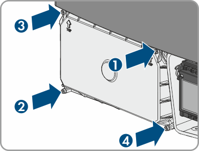
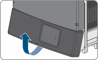
- If the lower enclosure lid is mounted, loosen all screws of the lower enclosure lid using an Allen key (AF 3) and lift the enclosure lid from below and remove it.
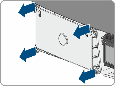
- Loosen the screws of the DC protective cover using an Allen key (AF 3) and remove the DC protective cover.
- Only use one opening per string.
- Do not enlarge the enclosure openings.
- Remove the adhesive tape from both openings.
- Insert one conduit fitting for each string into the opening and tighten from the inside using the counter nut.
- Attach one conduit for each string to the opening.
- Insert the DC cables through the conduit into the interior of the inverter.
- Strip the insulation of the DC cables by 18 mm (0.71 in).
- For connecting the string to INPUT A, connect the DC cables to the terminal block for the DC connection:
Connect the positive DC cable to the red terminal A+ and tighten with a screwdriver (torque: 5.8 Nm (51 in-lb)).
Connect the negative DC cable to the black terminal A- and tighten with a screwdriver (torque: 5.8 Nm (51 in-lb)).
- For connecting the string to INPUT B, connect the DC cables to the terminal block for the DC connection:
Connect the positive DC cable to the red terminal B+ and tighten with a screwdriver (torque: 5.8 Nm (51 in-lb)).
Connect the negative DC cable to the black terminal B- and tighten with a screwdriver (torque: 5.8 Nm (51 in-lb)).
- Ensure that all DC cables are securely in place.
- Close unused enclosure openings with UL-listed type 3R filler plugs.
- If required, you must connect additional grounding or equipotential bonding ( > Connecting Additional Grounding).
- If no additional grounding is to be connected, reattach the DC protective cover. Tighten all four screws with an Allen key (AF 3) in the order 1 to 4 (torque: 3.5 Nm (31 in-lb)).
 WARNING
Danger to life due to electric shock
NOTICE
Damage to the inverter due to moisture and dust intrusion
Electronic components in the inverter can be destroyed or damaged as a result of dust or moisture intrusion. The enclosure openings are suitable for conduits of 25.4 mm (1 in).