Connecting Additional Grounding
The inverter is equipped with a grounding terminal with two connection points on the DC side for additional grounding (e.g. use of a grounding electrode).
The grounding terminal is yellow/green and identified as follows:
-
Equipment grounding terminal: symbol

-
Grounding electrode conductor: labeling GEC
Cable requirements:
- The cable must be designed in accordance with the local installation requirements and for temperatures of over +90°C (+194°F).
- Cable type: copper wire
- Conductor cross-section: 10 mm² to 35 mm² (8 AWG to 2 AWG)
Requirement:
- The conduits must be correctly connected to the inverter.
Procedure:
- Disconnect the inverter from all voltage sources ( > Disconnecting the Inverter from Voltage Sources).
- If the protective cover is mounted, loosen the screws of the DC protective cover using an Allen key (AF 3) and remove the DC protective cover.
- Lead the equipment grounding conductor or the cable of the grounding electrode through the installed conduit into the inside of the inverter.
- Strip the equipment grounding conductor or the cable of the grounding electrode by 18 mm (0.71 in).
- Connect the equipment grounding conductor to the connection point with the symbol and tighten with a screwdriver (blade width: 6 mm (0.24 in)) (torque: 5.8 Nm (51 in-lb)).
- Connect the grounding electrode cable to the connection point GEC and tighten with a screwdriver (blade width: 6 mm (0.24 in)) (torque: 5.8 Nm (51 in-lb)).
- Make sure the equipment grounding conductor or the grounding electrode cable is firmly in place.
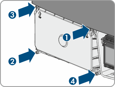
- Reattach the DC protective cover. Tighten all four screws with an Allen key (AF 3) in the order 1 to 4 (torque: 3.5 Nm (31 in-lb)).
 DANGER
Danger to life due to electric shock