
Recommissioning the Inverter
If you have disconnected the inverter from all voltage sources and want to recommission it, proceed as follows.
Requirements:
- The inverter must be correctly mounted.
- All cables must be correctly connected to the terminals.
- Unused openings for the DC connection in the inverter enclosure must be closed with UL-listed type 3R filler plugs.
- Unused openings for the Ethernet connection or the communication connection in the inverter enclosure must be sealed tightly. The factory-mounted filler plugs can be used for that purpose.
Procedure:
- Ensure that all DC cables are securely in place.
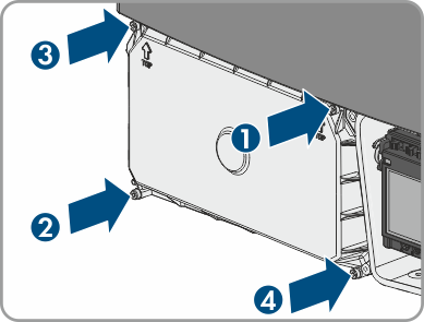
- Reattach the DC protective cover. Tighten all four screws with an Allen key (AF 3) in the order 1 to 4 (torque: 3.5 Nm (31 in-lb)).
- Make sure that the AC cable is routed so that it cannot be damaged by the partition in the lower enclosure lid.
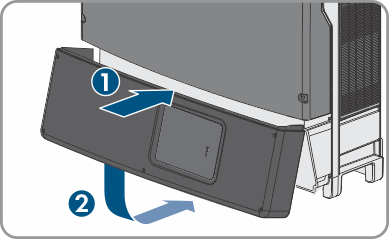
- Insert the lower enclosure lid from above and flip it down. Make sure that the ribbon cable of the communication assembly is not clamped and that the screws must protrude from the lower enclosure lid.
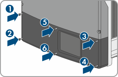
- Tighten all six screws with an Allen key (AF 3) in the order 1 to 6 (torque: 2.0 Nm (17.7 in-lb)). Make sure that the ribbon cable of the communication assembly is not clamped. By tightening the screws in the prescribed order, you avoid warping the enclosure lid, which would keep it from sealing correctly. Tip: If the screws fall out of the lower enclosure lid, insert the long screw into the lower middle hole and the five short screws into the other holes.
- Switch on all DC disconnectors between the inverter and the PV array.
- Switch on the circuit breaker and all AC disconnectors.
- The green LED is glowing. Feed-in operation begins.
- Once the DC input voltage is sufficiently high, feed-in operation begins.
- Rectify the error ( > Troubleshooting).
Green LED is flashing?
The DC input voltage is still too low.
The red LED is glowing?
There is probably an error.