
Procedure for Receiving a Replacement Device
Under fault conditions, the inverter may need to be replaced. If this is the case, you will receive a replacement device from SMA Solar Technology AG. If you received a replacement device, replace the defective inverter with the replacement device as described in this section.
Procedure:
Decommission the defective inverter.
Commission the replacement device.
Ship the defective inverter.
Decommissioning the Defective Inverter
- Disconnect the inverter from all voltage sources.
- Disconnect the DC cables from the terminal block for the DC connection using a screwdriver.
- Remove the AC cable from the inverter. Press the locking levers all the way upward and pull the conductors out of the terminal block for the AC cable.
- Press down the locking levers of the terminal block for the AC cable.
- Remove all connected grounding cables from the grounding terminal.
- If the multi-function relay or the SMA Power Control Module are used, remove the connection cable from the inverter.
- If other cables (e.g. data cables or network cables) are connected, remove them from the inverter.
- Remove any installed interfaces from the inverter (see the manual for the communication interface).
- Remove all conduits with cables from the inverter.
- Close all enclosure openings.
- Keep the DC load-break switch in a safe place as the replacement device will be delivered without the DC load-break switch.
- Wait 30 minutes before disassembling the inverter. This will allow the enclosure to cool down and thus prevent burn injuries.
- Carry and lift the inverter in an upright position with several people without tilting it.
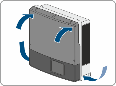
- Remove the inverter by lifting it vertically up and off the wall mounting bracket. With one hand grasp the recessed grip, and with the other hand support the top part of the enclosure. This will prevent the inverter from tipping forward.
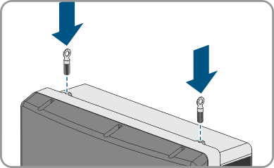
- If the inverter is to be transported and lifted with a crane, remove the filler plugs on the top of the inverter and screw the eye bolts into the threads.
 DANGER
Danger to life due to electric shock
 CAUTION
Risk of burns due to hot enclosure parts
CAUTION
Risk of injury when lifting the inverter, or if it is dropped
The inverter weighs 55 kg (121 lb). There is risk of injury if the inverter is lifted incorrectly or dropped while being transported or when attaching it to or removing it from the wall mounting bracket.
Commissioning the Replacement Device
NOTICE
Damage to the enclosure seal in subfreezing conditions
If you open the product when temperatures are below freezing, the enclosure seals can be damaged. Moisture can penetrate the product and damage it.
- Only open the product if the ambient temperature is not below -5°C (23°F).
- If a layer of ice has formed on the enclosure seal when temperatures are below freezing, remove it prior to opening the product (e.g. by melting the ice with warm air).
NOTICE
Damage to the product due to sand, dust and moisture ingress
Sand, dust and moisture penetration can damage the product and impair its functionality.
- Only open the product if the humidity is within the thresholds and the environment is free of sand and dust.
- Do not open the product during a dust storm or precipitation.
- Close tightly all enclosure openings.
- Only use listed rain-tight or liquid-tight conduit fittings to attach the conduits to the product.
NOTICE
Damage to the inverter due to electrostatic discharge
Touching electronic components can cause damage to or destroy the inverter through electrostatic discharge.
- Ground yourself before touching any component.
- Mount the replacement device and make the electrical connections.
- If needed, install interfaces in the replacement device and connect the interfaces (see the interface manual).
- Wait 20 minutes before opening the upper enclosure lid.
- If there is a label with "transport lid" affixed to the upper lid of the replacement device, replace the upper enclosure lid of the replacement device with the upper enclosure lid of the defective inverter.
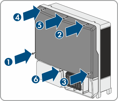
Loosen the screws of the upper enclosure lid using an Allen key (AF 4) and remove the enclosure lid.
Position the upper enclosure lid with the six screws and conical spring washers on the enclosure and tighten it using an Allen key (AF 4) in the order 1 to 6 (torque: 6 Nm ± 0.3 Nm).
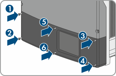
- Insert the lower enclosure lid from above and flip it down. Use the enclosure lid of the defective inverter for this if there is a label with "transport lid" affixed to the enclosure lid of the replacement device. Make sure that the ribbon cable of the communication assembly is not clamped and that the screws must protrude from the lower enclosure lid.
- Tighten all six screws in the lower enclosure lid with an Allen key (AF 3) in the order 1 to 6 (torque: 2 Nm ± 0.3 Nm). Make sure that the ribbon cable of the communication assembly is not clamped. By tightening the screws in the prescribed order, you avoid warping the lid, which would keep it from sealing correctly. Tip: If the screws fall out of the lower enclosure lid, insert the long screw into the lower middle hole and the five short screws into the other holes.
- Commission the replacement device. Remount the DC load-break switch of the defective inverter to the replacement device.
- Configure the replacement device.
- Replace the replacement device in the communication product.
DANGER
Danger to life due to high voltages
Once disconnected from voltage sources, residual voltages can remain in the product that should be allowed to discharge completely.
Shipping the Defective Inverter
- If necessary, position the upper enclosure lid with the six screws and conical spring washers on the enclosure and tighten it using an Allen key (AF 4) in the order 1 to 6 (torque: 6 Nm ± 0.3 Nm).
- Insert the lower enclosure lid from above and flip it down. Make sure that the ribbon cable of the communication assembly is not clamped and that the screws must protrude from the lower enclosure lid.
- Tighten all six screws of the lower enclosure lid using an Allen key (AF 3) in the order 1 to 6 (torque: 2.0 Nm (17.7 in-lb.)). Make sure that the ribbon cable of the communication assembly is not clamped. By tightening the screws in the prescribed order, you avoid warping the lid, which would keep it from sealing correctly. Tip: If the screws fall out of the lower enclosure lid, insert the long screw into the lower middle hole and the five short screws into the other holes.
- Pack the defective inverter in the packaging of the replacement device and arrange with SMA Solar Technology AG for it to be picked up.