
Preparing for mounting and connection
 Qualified person
 DANGER
Danger to life due to electric shock when live cables are touched
High voltages are present on the AC and DC cables. Touching live cables results in death or lethal injuries due to electric shock.
- Do not touch non-insulated parts or cables.
- Disconnect the AC circuit breaker and secure it against reconnection.
- Disconnect the PV array from the inverter via an external DC load-break switch (e.g. via a PV junction including a load-break switch). Switch off and secure the DC load-break switch against reconnection.
- Ensure that all cables to be connected are de-energized.
- Wear suitable personal protective equipment for all work on the product.
Procedure:
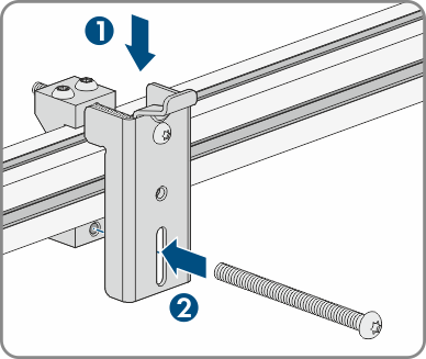
- Mark the position for the mounting brackets.
- Hook each mounting bracket onto the profile rail and insert the screw (M8x105).
- Fasten all four screws of each mounting bracket hand-tight (TX40).
- Ensure the correct position of the mounting brackets by hooking in the mounting template. If the position is incorrect, move the mounting brackets to the correct position.
- Tighten all four screws of each mounting bracket (TX40, torque: 12 Nm ± 2 Nm).
- Clip the mounting template into the mounting brackets.
- Align the cables by means of the mounting template and shorten if necessary. Take the product depth of 400 mm into account.
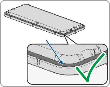
- Ensure on the connection plate that the seal is present and undamaged.
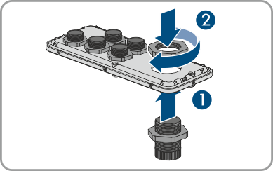
- Thread the swivel nuts of the cable glands over the cables.
- Attach the cable glands to the connecting plate. For the connection of one PV combiner box, insert the M32x1.5 cable glands with a clamping range of 18 mm to 25 mm into the front two openings and the M32x1.5 cable glands with a clamping range of 12 mm to 20 mm into the rear two openings and insert the two sealing plugs there. For the connection of two PV combiner boxes, insert the M32x1.5 cable glands with a clamping range of 12 mm to 20 mm in all four openings.
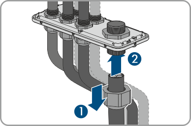
- Lead the cables through the cable glands in the connecting plate and align the connecting plate by means of the mounting template.
- Remove the mounting template.
- Mount the product .
Also see: