
Connecting Signal Source to Digital Input DI 5-6
 Qualified person
Additionally required material (not included in the scope of delivery):
1 relay for the grid and PV system protection (break contact)
1 fast-stop switch (break contact)
Requirements:
The signal source must be technically suitable for connection to the digital inputs ( > Technical Data).
Procedure:
- Connect the connection cable to the digital signal source (see the manual from manufacturer).
- Disconnect the inverter from all voltage sources ( > Disconnecting the Inverter from Voltage Sources).
- Unscrew the swivel nut from the cable gland.
- Remove the four-hole cable support sleeve from the cable gland.
- Remove the plug from one of the enclosure openings and cut into the enclosure opening with a utility knife.
- Insert the cable into the enclosure opening.
- Press the four-hole cable support sleeve with the cable into the cable gland and guide the cable to slot DI 5-7. Ensure that the unused enclosure openings of the four-hole cable support sleeve are sealed with sealing plugs.
- Dismantle the cable by 150 mm.
- Strip off the conductor insulation by 6 mm.
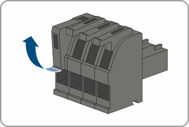
- Release the conductor entries on the supplied 4-pole plug.
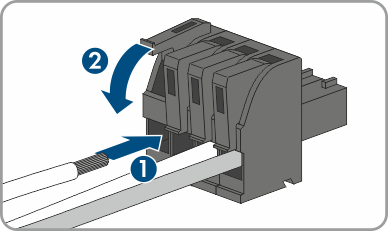
- Connect the conductors of the connection cable to the supplied 4-pole plug. To do so, plug the conductors into the conductor entries and close the conductor entries. Observe the plug assignment.
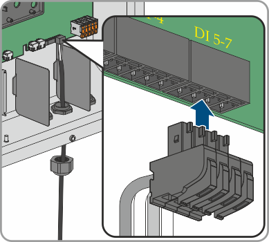
- Plug the 4-pole plug into the socket DI 5-7 on the product. Observe the pin assignment.
- Ensure that the plug is securely in place.
- Ensure that all conductors are correctly connected.
- Ensure that the conductors sit securely in the terminal points.
- Tighten the swivel nut on the cable gland hand-tight.
Also see: